AIR CONDITIONING
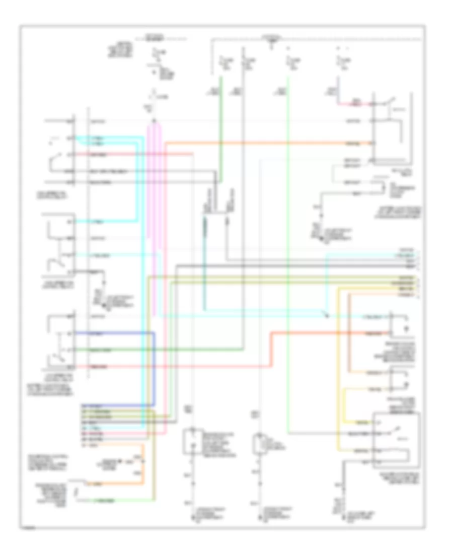
2.0L
2.0L, Manual A/C Wiring Diagram (1 of 2) for Mazda Tribute DX 2003

List of elements for 2.0L, Manual A/C Wiring Diagram (1 of 2) for Mazda Tribute DX 2003:
- (at left front of engine compartment) g6
- (at lower left side of dash) g12
- (at right front of engine compartment) g3
- (at right front of engine compartment) g5
- A/c clutch relay
- A/c clutch solenoid
- A/c compressor clutch diode
- Battery junction box (on left front corner of engine compartment)
- Blower motor relay (behind lower left center of dash)
- Central junction box (below left end of dash)
- Cylinder head temperature (cht) sensor (on right front of cylinder head)
- Engine controls system
- Engine cooling fan motor 1 (on left side of engine compartment, behind radiator)
- Engine cooling fan motor 2 (on right side of engine compartment, behind radiator)
- Front blower motor (behind right side of dash)
- Fuse 15a
- Fuse 2 5a
- Fuse 40a
- Fuse 9 3a
- High speed fan control relay 1
- Hot at all times
- Hot in on or start
- Low speed fan control relay
- Medium speed fan control relay
- Pcm power diode
- Powertrain control module (pcm) (in recess on upper center of firewall)
- X-270b
- X-270c
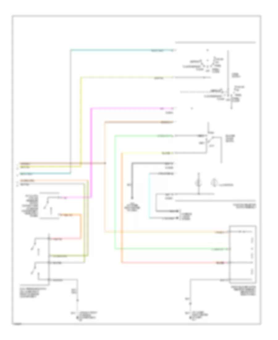
2.0L, Manual A/C Wiring Diagram (2 of 2) for Mazda Tribute DX 2003
List of elements for 2.0L, Manual A/C Wiring Diagram (2 of 2) for Mazda Tribute DX 2003:
- (at lower right center of dash) g11
- (at right front of engine compartment) g5
- A/c
- A/c clutch cycling pressure switch (on right side of engine compartment, near strut tower)
- Blower motor switch
- Defrost
- Dual pressure switch (on lower right front of engine compartment)
- Floor
- Floor/defrost
- Front blower motor resistor assembly (behind right side of dash)
- Function selector switch assembly
- G-294a
- G-294b
- G-294c
- G10 (at lower right center of dash)
- High
- Illumination
- Interior lights system
- Low
- Max a/c
- Med 1
- Med 2
- Mode switch
- Off
- Panel
- Panel/ floor
3.0L
3.0L, Manual A/C Wiring Diagram (1 of 2) for Mazda Tribute DX 2003
List of elements for 3.0L, Manual A/C Wiring Diagram (1 of 2) for Mazda Tribute DX 2003:
- (at left front of engine compartment) g6
- (at lower left side of dash) g12
- (at right front of engine compartment) g3
- (at right front of engine compartment) g5
- 87a
- A/c clutch relay
- A/c clutch solenoid
- A/c compressor clutch diode
- Battery junction box (on left front corner of engine compartment)
- Battery junction box (on left front corner of engine compartment)
- Blower motor relay (behind lower left center of dash)
- Central junction box (below left end of dash)
- Engine controls system
- Engine coolant temperature (ect) sensor (on rear of right cylinder head)
- Engine cooling fan motor 1 (on left side of engine compartment, behind radiator)
- Engine cooling fan motor 2 (on right side of engine compartment, behind radiator)
- Front blower motor (behind right side of dash)
- Fuse 15a
- Fuse 3a
- Fuse 40a
- Fuse 50a
- High speed fan control relay 1
- High speed fan control relay 2
- Hot at all times
- Hot in on or start
- Late production
- Low speed fan control relay
- Pcm power diode
- Powertrain control module (pcm) (in recess on upper center of firewall)
- Production early
- X-270b
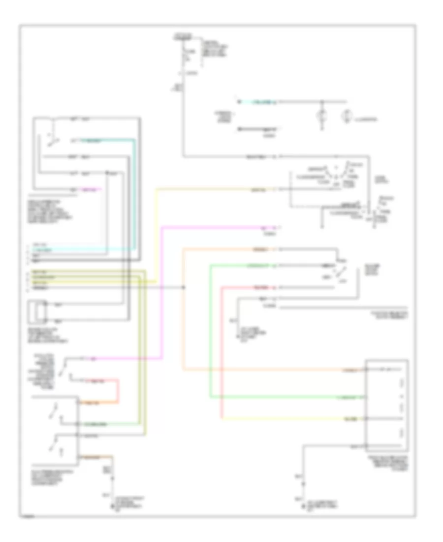
3.0L, Manual A/C Wiring Diagram (2 of 2) for Mazda Tribute DX 2003
List of elements for 3.0L, Manual A/C Wiring Diagram (2 of 2) for Mazda Tribute DX 2003:
- (at lower right center of dash) g10
- (at lower right center of dash) g11
- (at right front of engine compartment) g5
- 87a
- A/c
- A/c clutch cycling pressure switch (on right side of engine compartment, near strut tower)
- Blower motor switch
- Central junction box (below left end of dash)
- Defrost
- Dual pressure switch (on lower right front of engine compartment)
- Engine cooling fan resistor (at left front of engine compartment)
- Floor
- Floor/defrost
- Front blower motor resistor assembly (behind right side of dash)
- Function selector switch assembly
- Fuse 5a
- G-294a
- G-294b
- G-294c
- High
- Hot in on or start
- Illumination
- Interior lights system
- Low
- Max a/c
- Med 1
- Med 2
- Medium speed fan control relay (early production) (on lower left front of engine compartment, near headlight)
- Mode switch
- Off
- Panel
- Panel/ floor
- X-270c