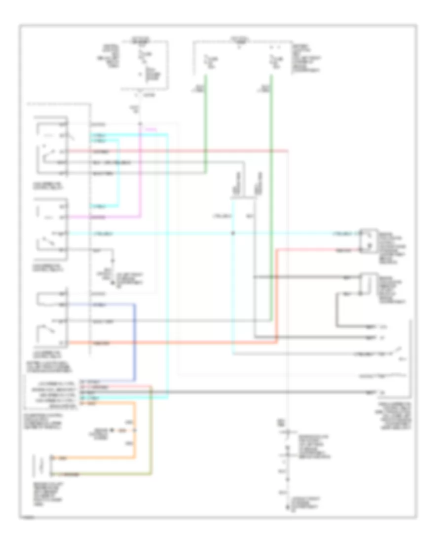
COOLING FAN
2.0L
2.0L, Cooling Fan Wiring Diagram for Mazda Tribute DX 2003

List of elements for 2.0L, Cooling Fan Wiring Diagram for Mazda Tribute DX 2003:
- (at left front of engine compartment) g6
- (at right front of engine compartment) g3
- Battery junction box (on left front corner of engine compartment)
- Central junction box (below left end of dash)
- Cyl temp sensor input
- Cylinder head temperature (cht) sensor (on right front of cylinder head)
- Engine controls system
- Engine cooling fan motor 1 (on left side of engine compartment, behind radiator)
- Engine cooling fan motor 2 (on right side of engine compartment, behind radiator)
- Fuse 3a
- Fuse 40a
- High speed fan control relay 1
- High speed rly ctrl 1
- Hot at all times
- Hot in on or start
- Low speed fan control relay
- Low speed rly ctrl
- Med speed rly ctrl
- Medium speed fan control relay
- Pcm power diode
- Powertrain control module (pcm) (in recess on upper center of firewall)
- Signal return
- X-270b
3.0L
3.0L, Cooling Fan Wiring Diagram for Mazda Tribute DX 2003
List of elements for 3.0L, Cooling Fan Wiring Diagram for Mazda Tribute DX 2003:
- (at left front of engine compartment) g6
- (at right front of engine compartment) g3
- 87a
- Battery junction box (on left front corner of engine compartment)
- Central junction box (below left end of dash)
- Early production
- Engine controls system
- Engine cool sens input
- Engine coolant temperature (ect) sensor (on rear of right cylinder head)
- Engine cooling fan motor 1 (on left side of engine compartment, behind radiator)
- Engine cooling fan motor 2 (on right side of engine compartment, behind radiator)
- Engine cooling fan resistor (at left front of engine compartment)
- Fuse 3a
- Fuse 50a
- High speed fan control relay 1
- High speed fan control relay 2
- High speed rly ctrl 1
- Hot at all times
- Hot in on or start
- Late production
- Low speed fan control relay
- Low speed rly ctrl
- Med speed rly ctrl
- Medium speed fan control relay (early production) (on lower left front of engine compartment, near headlight)
- Pcm power diode
- Powertrain control module (pcm) (in recess on upper center of firewall)
- Signal return
- X-270b