SUPPLEMENTAL RESTRAINTS
Supplemental Restraints Wiring Diagram for Mazda Tribute DX 2003
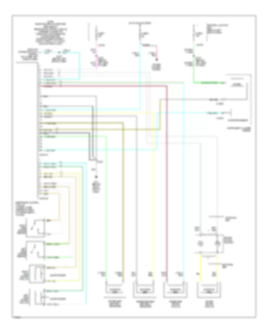
List of elements for Supplemental Restraints Wiring Diagram for Mazda Tribute DX 2003:
- Air bag
- Air bag sliding contact
- C-220a
- C-220b
- Central junction box (below left end of dash)
- Cruise control system
- Data link connector (dlc) (partial) (on lower left side of dash)
- Driver air bag module
- Driver seat seat belt tensioner
- Fuse 4 10a
- Fuse 5 5a
- Fuse 7 10a
- G13 (behind right side of dash)
- Hot in run or start
- Instrument cluster (meter)
- Left side air bag module
- Left side air bag sensor
- Microprocessor
- Note: shorting bar connectors are used on restraints control module harness connector when module connector is disconnected shorting bars connect: s-2041a: pins 3-4, 6-7 & 20-21 s-2041b: pins 2-3 & 5-6
- Of dash)
- Passenger air bag module
- Passenger seat seat belt tensioner
- Restraints control module (under lower center of dash, on transmission tunnel)
- Right side air bag module
- Right side air bag sensor
- S-2041a
- S-2041b
- S-205
- S-219 (behind left side of dash)
- Shorting bar
- X-270c
- X-270d
 English