AIR CONDITIONING
Manual A/C Wiring Diagram (1 of 2) for Mazda Tribute Hybrid Grand Touring 2011

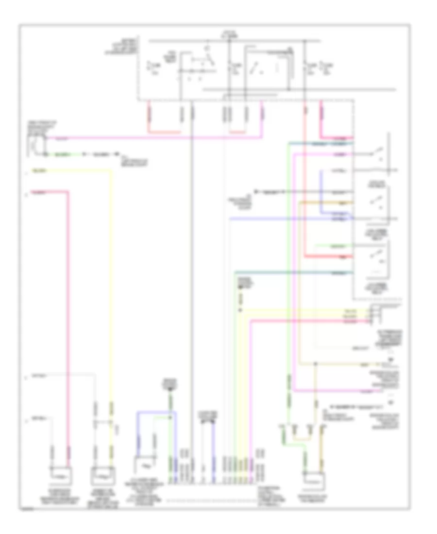
List of elements for Manual A/C Wiring Diagram (1 of 2) for Mazda Tribute Hybrid Grand Touring 2011:
- 0740-101
- 0740-102
- Battery junction box (on left side of engine compt)
- Blower motor relay
- C-211
- C-212
- C-237
- C-238
- Computer data lines system
- Defogger system
- Front blower motor (right side of dash)
- Front blower motor resistor assembly (under right side of dash)
- Fuse 10a
- Fuse 40a
- Fuse 5a
- G12 (lower right side of dash)
- G14 (lower left side of dash)
- Hot at all times
- Hot in run or acc
- Hot in run or start
- J-2280a
- J-2280b
- J-2280e
- Manual climate control module (center of dash)
- Mode door actuator (center of dash)
- Recirculation blend door actuator (dash)
- Seats system
- Smart junction box (behind center of dash)
- Temperature blend door actuator (right side of dash)
- Wiper/ washer system
Manual A/C Wiring Diagram (2 of 2) for Mazda Tribute Hybrid Grand Touring 2011
List of elements for Manual A/C Wiring Diagram (2 of 2) for Mazda Tribute Hybrid Grand Touring 2011:
- (2.5l)
- (3.0l)
- (right front of engine compt) a/c clutch solenoid
- 0140-175b
- 0140-175e
- 0140-275b
- 0140-275e
- 2.5l
- 3.0l
- A/c clutch relay
- A/c pressure transducer (left side of engine compt)
- Ambient air temperature sensor (behind left side of front grille)
- Battery junction box (on left side of engine compt)
- C-212
- Computer data lines system
- Cooling fan relay
- Cylinder head temperature sensor (2.5l: on right front of cylinder head) (3.0l: front center of engine)
- Engine control system
- Engine cooling fan motor 1 (front of engine compt)
- Engine cooling fan motor 2 (front of engine compt)
- Engine cooling fan resistor
- Evaporator discharge temperature sensor (right side of dash)
- Fuse 10a
- Fuse 40a
- G11 (left front of engine compt)
- G3 (right front of engine compt)
- High speed fan control relay
- Hot at all times
- Low speed fan control relay
- Pcm power relay
- Powertrain control module (pcm) (upper center of firewall)
- Red