WARNING SYSTEMS
Warning Systems Wiring Diagram for Mazda Tribute Hybrid Grand Touring 2011
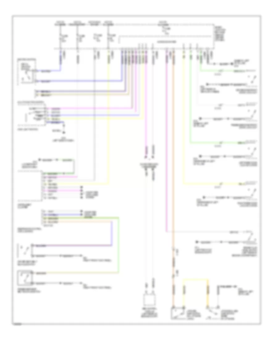
List of elements for Warning Systems Wiring Diagram for Mazda Tribute Hybrid Grand Touring 2011:
- (base of left "b" pillar) g19
- 0810-102
- Abs control module (left rear of engine compt)
- Auto 1
- Brake fluid level switch (left rear of engine compartment)
- C-311
- C-312
- C-313
- C-314
- C-408
- C-922
- Computer data lines system
- Driver seat belt buckle switch
- Driver side front door lock unit
- Fuse 10a
- Fuse 20a
- Fuse 5a
- G11 (left front of engine compt)
- G13 (lower right side of dash)
- G15 (left side of dash)
- G18 (base of left "b" pillar)
- G18 (near base of left "b" pillar)
- G19 (base of left "b" pillar)
- G21 (right front kick panel)
- G24 (left rear of vehicle chassis)
- Hot at all times
- Hot in run or acc
- Hot in run or start
- Ignition switch
- Instrument cluster
- J-2280a
- J-2280b
- J-2280c
- J-2280d
- J-2280f
- Key in ignition switch
- Left rear door lock actuator
- Liftgate ajar switch (on liftgate latch)
- Liftgate glass ajar switch (base of liftgate)
- Low
- Main light switch
- Microcomputer
- Multi-function switch
- Off
- Park
- Passenger seat belt buckle switch
- Passenger side front door lock unit
- Restraints control module (rcm)
- Right rear door lock actuator
- Smart junction box (sjb) (behind center of dash)
 English