ANTI-LOCK BRAKES
Anti-lock Brakes Wiring Diagram for Mazda Tribute Hybrid Grand Touring 2011
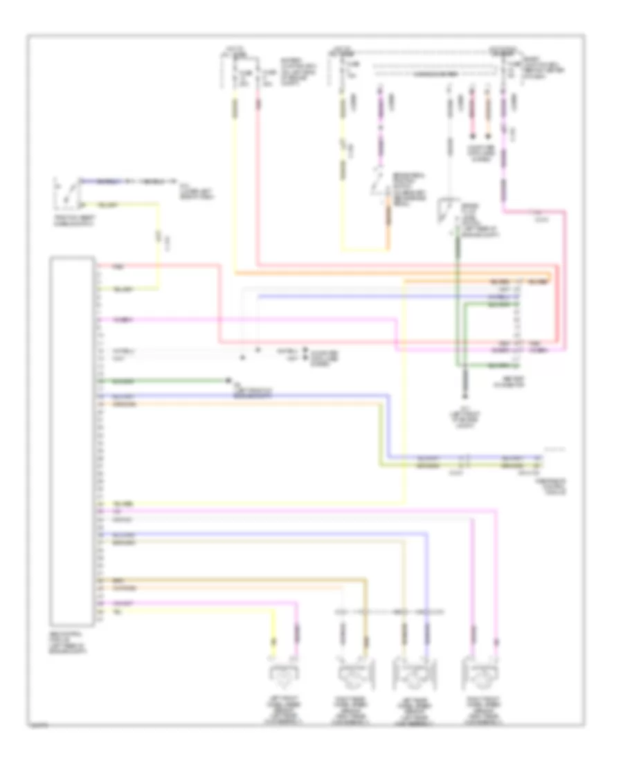
List of elements for Anti-lock Brakes Wiring Diagram for Mazda Tribute Hybrid Grand Touring 2011:
- 0810-102
- Abs control module (left rear of engine compt)
- Abs test connector
- Battery junction box (on left side of engine compt)
- Brake fluid level switch (left rear of engine compt)
- Brake pedal position switch (on bracket, above brake pedal)
- C-210
- C-212
- C-215
- Computer data lines system
- Fuse 15a
- Fuse 20a
- Fuse 50a
- Fuse 5a
- G11 (left front of engine compt)
- G14 (lower left side of dash)
- G5 (left front of engine compt)
- Hot at all times
- Hot in run or start
- J-2280b
- J-2280d
- J-2280f
- Left front wheel speed sensor (left rear hub assembly)
- Left rear wheel speed sensor (left rear hub assembly)
- Microcomputer
- Red
- Restraints control module
- Right front wheel speed sensor (right rear hub assembly)
- Right rear wheel speed sensor (right rear hub assembly)
- Smart junction box (behind center of dash)
- Traction assist disable switch
 English