AIR CONDITIONING
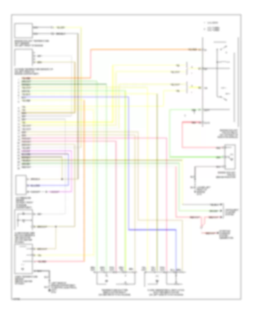
Automatic A/C Wiring Diagram (1 of 2) for Volvo V70 2000

List of elements for Automatic A/C Wiring Diagram (1 of 2) for Volvo V70 2000:
- (behind right side of dash, near "a" pillar) g901
- (not used)
- 2.3l turbo,
- 2.4l dohc
- 2.4l turbo
- 87a
- A/c pressure switch (pressostat) (on right rear of engine compartment)
- A/c relay (on engine compartment relay/fuse box, position no 4)
- A/c switch solenoid (on a/c compressor)
- A10
- A11
- A12
- A13
- A14
- A15
- A16
- A17
- A18
- A19
- A20
- A21
- A22
- A23
- A24
- A25
- A26
- A27
- A28
- A29
- A30
- A39
- A40
- A58
- A60
- A61
- A68
- B27
- B32
- B44
- Blower fan (behind right side of dash, on hvac housing)
- Blower fan power unit (on right side of hvac housing)
- C10
- Central electrical unit (on left rear of engine compartment)
- Data link connector (dlc) (on center console, near shift lever)
- Ecc climate control module
- Engine compartment relay/fuse box (on left rear of engine compartment, next to strut tower)
- Engine control module (on right front inner fender panel, in control module box)
- Fuse 10a
- Fuse 15a
- Fuse 2 15a (or fuse 5 20a)
- Fuse 25a
- Fuse 60a
- Hot at all times
- Hot in acc or on
- Hot in on or start
- Illum
- Interior lights system (rheostat)
- Pnk
- Recirculation shutter servo motor (on right side of hvac housing)
- Temperature shutter servo motor (left) (on left side of hvac housing)
Automatic A/C Wiring Diagram (2 of 2) for Volvo V70 2000
List of elements for Automatic A/C Wiring Diagram (2 of 2) for Volvo V70 2000:
- (left rear of engine compartment, in central electrical unit) g104
- 2.3l turbo, 2.4l turbo
- 2.4l dohc
- A/c pressure sensor (on right front of engine compartment)
- Alarm/immobilizer ecc sun sensor & led indicator (on top center of dash)
- Cabin temperature sensor (behind center of dash)
- Engine coolant fan (fc) (behind radiator)
- Engine coolant fan (fc) relay (on top right of radiator shroud)
- Engine coolant temperature (ect) sensor (on left front of engine)
- Floor, defroster & ventilation shutter servo motor (on left side of hvac housing)
- Front of engine) g110
- In1
- In2
- Instrument cluster system
- Nca
- Out1
- Out2
- Outside temperature sensor (i/p) (on left front of engine compartment)
- Red
- Starting/ charging system (generator)
- Temperature shutter servo motor (right) (on center of hvac housing)
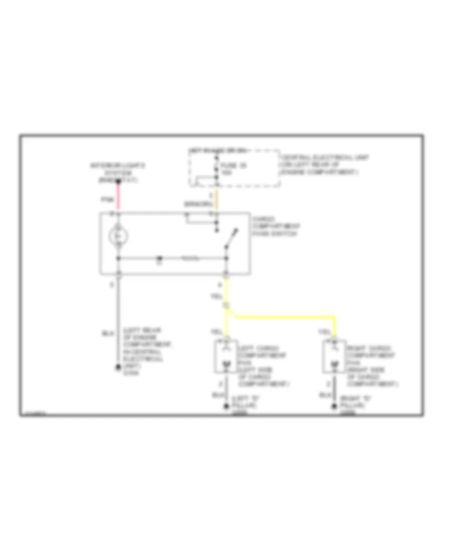
Cargo Compartment Fans Wiring Diagram for Volvo V70 2000
List of elements for Cargo Compartment Fans Wiring Diagram for Volvo V70 2000:
- (left "d" pillar) g999
- (left rear of engine compartment, in central electrical unit) g104
- (right "d" pillar) g998
- Cargo compartment fans switch
- Central electrical unit (on left rear of engine compartment)
- Fuse 35 10a
- Hot in acc or on
- Interior lights system (rheostat)
- Left cargo compartment fan (left side of cargo compartment)
- Pnk
- Right cargo compartment fan (right side of cargo compartment)
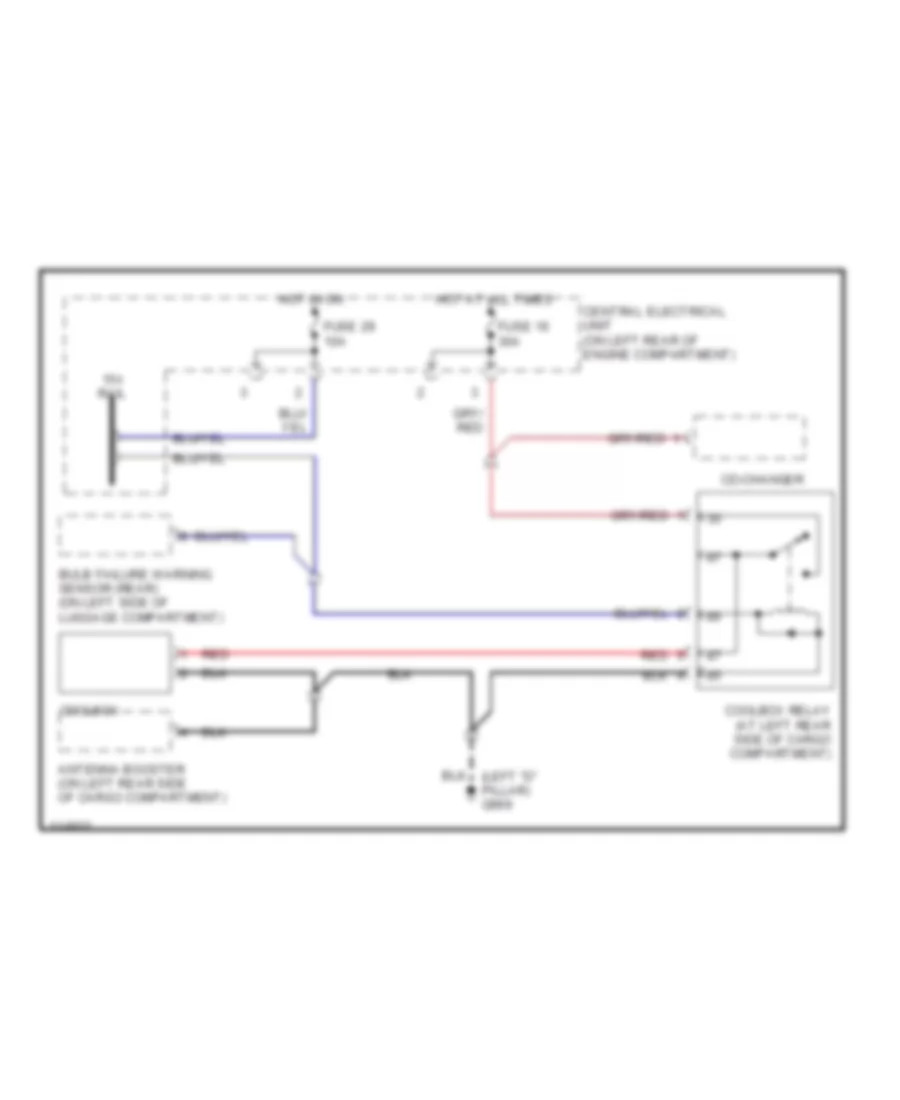
Cool Box Wiring Diagram for Volvo V70 2000
List of elements for Cool Box Wiring Diagram for Volvo V70 2000:
- 15-i rail
- Antenna booster (on left rear side of cargo compartment)
- Bulb failure warning sensor (rear) (on left side of luggage compartment)
- Cd-changer
- Central electrical unit (on left rear of engine compartment)
- Coolbox
- Coolbox relay (at left rear side of cargo compartment)
- Fuse 16 30a
- Fuse 29 10a
- Hot at all times
- Hot in on
- Red
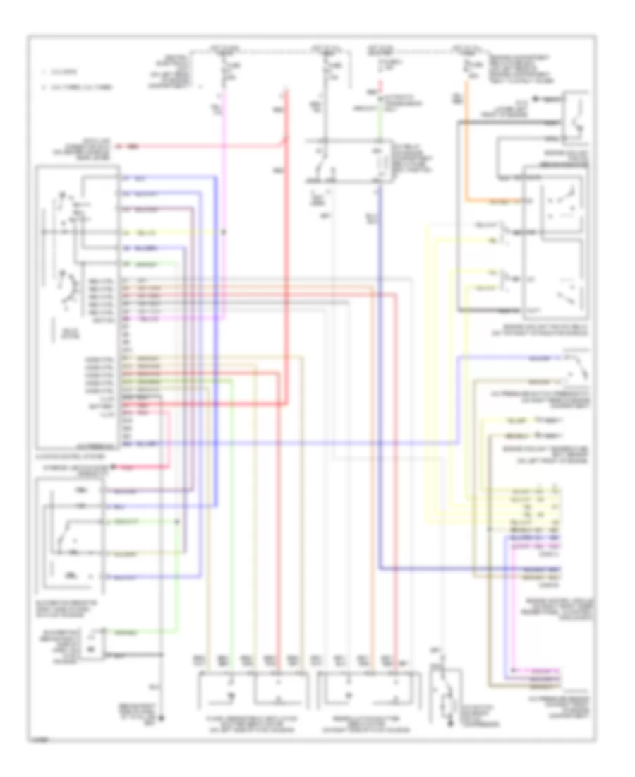
Manual A/C Wiring Diagram for Volvo V70 2000
List of elements for Manual A/C Wiring Diagram for Volvo V70 2000:
- (behind right side of dash, at "a" pillar) g901
- (not used)
- (on center console, near lever)
- 2.3l turbo, 2.4l turbo
- 2.4l dohc
- 87a
- A/c press sw
- A/c pressure sensor (on right front of engine compartment)
- A/c pressure switch (pressostat) (on right rear of engine compartment)
- A/c relay (on engine compartment relay/fuse box, position 4)
- A/c switch solenoid (on a/c compressor)
- A21
- A39
- A40
- A58
- A60
- A61
- A68
- Automatic transmission only
- B10
- B11
- B12
- B13
- B14
- B15
- B16
- B17
- B18
- B19
- B20
- B21
- B22
- B32
- B44
- Battery
- Blower fan (behind right side of dash, on hvac housing)
- Blower fan resistor (right side of dash, on hvac housing)
- C1 nca
- C2 nca
- Central electrical unit (on left rear of engine compartment)
- Climate control system
- Conn a
- Conn b
- Data link connector (dlc)
- Engine compartment relay/fuse box (on left rear of engine compartment, next to strut tower)
- Engine control module (on right front inner fender panel, in control module box)
- Engine coolant fan (fc) (behind radiator)
- Engine coolant fan (fc) relay (on top right of radiator shroud)
- Engine coolant temperature (ect) sensor (on left front of engine)
- Floor, defroster & ventilation shutter servo motor (on left side of hvac housing)
- Fuse 15a
- Fuse 2 15a
- Fuse 25a
- Fuse 60a
- G110 (lower left front of engine)
- Hot at all times
- Hot in acc or on
- Hot in on or start
- Ignition
- Illum
- In1
- In2
- Interior lights system (rheostat)
- Mode ctrl
- Nca
- Out1
- Out2
- Pnk
- Rec ctrl
- Recirculation shutter servo motor (on right side of hvac housing)
- Red
- Solid state