AUTOMOTIVE ELECTRICIANS PORTAL

ANTI-THEFT – Volvo V70 2000 – SYSTEM WIRING DIAGRAMS

ANTI-THEFT

Anti-theft Alarm Wiring Diagram for Volvo V70 2000

Anti-theft Alarm Wiring Diagram for Volvo V70 2000 https://portal-diagnostov.com/license.html
https://portal-diagnostov.com/license.html Automotive Electricians Portal FZCO Automotive Electricians Portal FZCO
Download PDF file

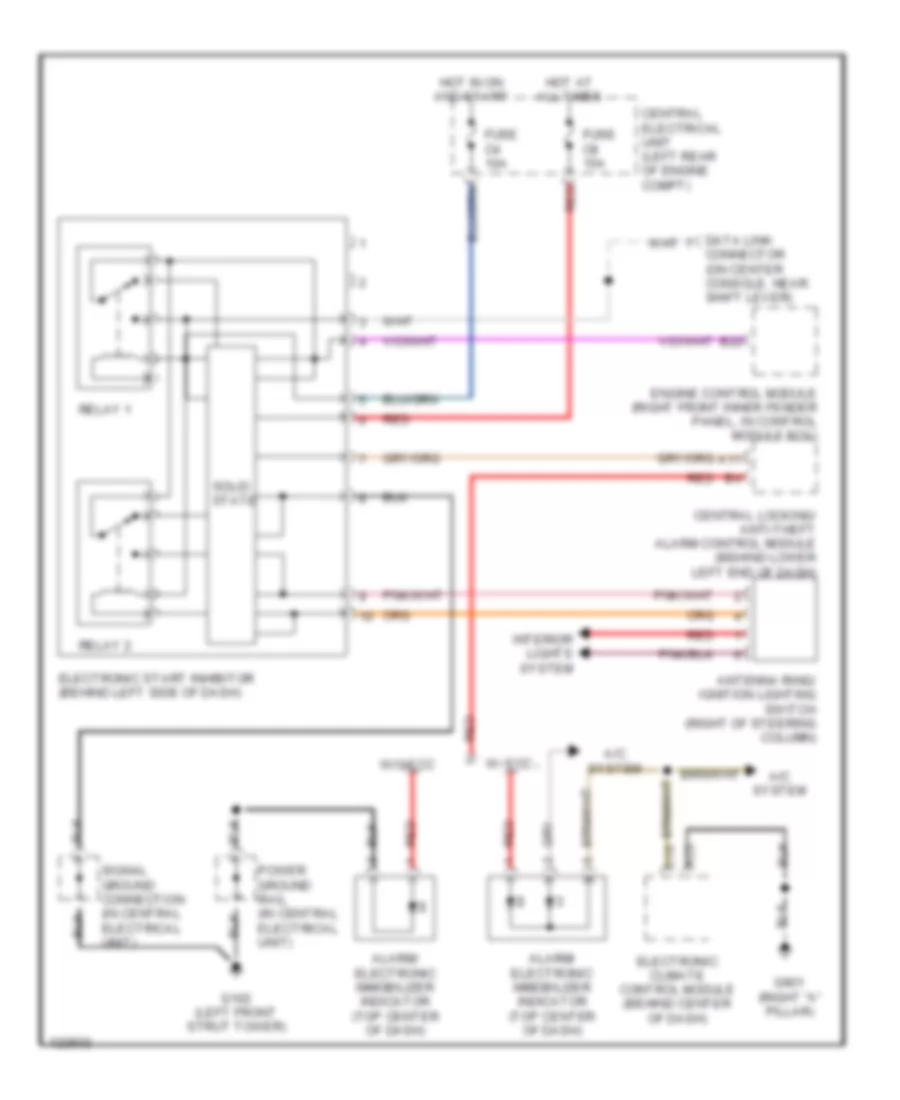
List of elements for Anti-theft Alarm Wiring Diagram for Volvo V70 2000:

  • (right "a" pillar)
  • (right side of engine compt)
  • 15i-rail connector
  • A/c system
  • A10
  • A11
  • A12
  • A13
  • A14
  • A15
  • A16
  • A17
  • A18
  • A19
  • A20
  • A21
  • A22
  • A23
  • A24
  • A25
  • A26
  • Alarm horn (rear center of engine compt)
  • Alarm horn relay (on central electrical unit, position 202)
  • Alarm siren
  • Alarm/ electronic immobilizer indicator
  • B10
  • B11
  • B12
  • B13
  • B14
  • B15
  • B16
  • B17
  • B18
  • B19
  • B20
  • B21
  • C10
  • Car tilt sensor (on right rear corner of vehicle)
  • Central electrical unit (left rear of engine compt)
  • Central locking/ anti-theft alarm control module (behind lower left end of dash)
  • Central locking/alarm remote control unit (behind upper left side of dash)
  • Circuit
  • Data link connector (on center console, near shift lever)
  • Door locks system
  • Electronic climate control module (behind center of dash)
  • Exterior lights system (turn signal)
  • Fuse c10 10a
  • Fuse c13 15a
  • Fuse c18 10a
  • Fuse c29 10a
  • Fuse c3 10a
  • Fuse c6 20a
  • G102 (left front strut tower)
  • G404 (left rear side of trunk)
  • G900 (left "a" pillar)
  • G901
  • Glass breakage sensor (behind right side of dash)
  • Hood alarm switch (left front of eng compt)
  • Hot at all times
  • Hot in on or start
  • Hot w/ overload relay 15i energized
  • Ignition switch
  • Immobilizer
  • Instrument cluster system
  • Key in ignition switch
  • Left movement detector (left "b" pillar)
  • Left rear side window alarm lead (v70 only)
  • Microphone
  • Nca
  • Power ground rail (in central electrical unit)
  • Rear window heated element
  • Red
  • Right movement detector (right "b" pillar)
  • Right rear side window alarm lead (v70 only)
  • Solid state
  • Starter motor relay (in eng compt relay/fuse box position 3)
  • W/ ecc
  • W/o ecc

Immobilizer Wiring Diagram for Volvo V70 2000

Immobilizer Wiring Diagram for Volvo V70 2000 https://portal-diagnostov.com/license.html
https://portal-diagnostov.com/license.html Automotive Electricians Portal FZCO Automotive Electricians Portal FZCO
Get access to all wiring diagrams of the carDownload PDF file

List of elements for Immobilizer Wiring Diagram for Volvo V70 2000:

  • A/c system
  • A11
  • A23
  • Alarm/ electronic immobilizer indicator (top center of dash)
  • Antenna ring/ ignition lighting switch (right of steering column)
  • B22
  • C10
  • Central electrical unit (left rear of engine compt)
  • Central locking/ anti-theft alarm control module (behind lower left end of dash)
  • Connector (on center console, near shift lever)
  • Data link
  • Electronic climate control module (behind center of dash)
  • Electronic start inhibitor (behind left side of dash)
  • Engine control module (right front inner fender panel, in control module box)
  • Fuse c4 10a
  • Fuse c8 15a
  • G102 (left front strut tower)
  • G901 (right "a" pillar)
  • Hot at all times
  • Hot in on and start
  • Interior lights system
  • Power ground rail (in central electrical unit)
  • Red
  • Relay 1
  • Relay 2
  • Signal ground connection (in central electrical unit)
  • Solid state
  • W/ ecc
  • W/o ecc