ANTI-LOCK BRAKES
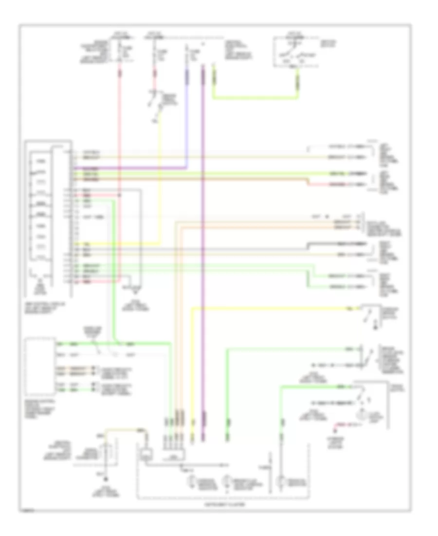
Anti-lock Brake Wiring Diagrams for Volvo V70 2000
List of elements for Anti-lock Brake Wiring Diagrams for Volvo V70 2000:
- (1999)
- 15a
- A15
- A18
- A19
- A20
- A28
- A29
- A37
- A55
- Abs control module (on left rear of engine compt)
- Abs pump motor
- Acc
- B13
- B16
- B30
- Brake fluid level sensor (in brake master cylinder reservoir)
- Brake fluid level warning indicator
- Brake pedal switch
- Cdm
- Central electrical unit (left rear of engine compt)
- Computer data lines system (diesel w/ a/t)
- Computer data lines system (except diesel)
- Cpu
- Data link connector (center console, near shift lever)
- Engine compartment relay/fuse box (left rear of engine compt)
- Engine control module (on right front inner fender panel)
- Fuse
- Fuse a4 50a
- Fuse c11 10a
- Fuse c4 10a
- G102 (left front shock tower)
- G102 (left front strut tower)
- Gasoline engines w/ m/t
- Hot at all times
- Ignition switch
- Illum- ination lamp
- Instrument cluster
- Interior lights system
- Left front abs sensor (on wheel hub)
- Left rear abs sensor (on wheel hub)
- Nca
- Off
- Parking brake on indicator
- Parking brake switch
- Pnk
- Red
- Right front abs sensor (on wheel hub)
- Right rear abs sensor (on wheel hub)
- Signal ground connector
- Start
- Tracs on indicator
- Tracs switch
 English