ANTI-LOCK BRAKES
Anti-lock Brakes Wiring Diagram for Acura TL 2006
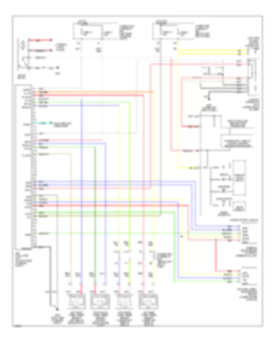
List of elements for Anti-lock Brakes Wiring Diagram for Acura TL 2006:
- (left side of dash) junction connector c506
- +b-fsr
- +b-mr
- A13
- A14
- Abs ind
- B18
- Brake system ind
- C10
- C12
- Can-h
- Can-l
- Computer data lines system
- Diag-k
- Drive circuit
- E12
- Fast controller area network transceiver
- Fl +b
- Fl-gnd
- Fr +b
- Fr-gnd
- Fuse 17 30a
- Fuse 18 15a
- Fuse 18 40a
- Fuse 21 7.5a
- G203 (right side of engine compt)
- G501
- G503 (under left side of dash)
- Gauge control module
- Glat
- Gnd
- Hot at all times
- Hot in on or start
- Ig1
- Interior lights system
- Junction connector c512 (under middle of dash)
- Left front wheel speed sensor (left side of engine compt)
- Left rear wheel speed sensor (under left rear of vehicle)
- Mr-gnd
- Pnk
- Red
- Right front wheel speed sensor (on right side of engine compt)
- Right rear wheel speed sensor (under right rear of vehicle)
- Rl +b
- Rl-gnd
- Rr +b
- Rr-gnd
- S-gnd
- Steering angle sensor (on side of steering column)
- Stra
- Strb
- Strz
- Svcc
- Under-dash fuse/relay box (behind left end of dash)
- Under-hood fuse/relay box (left rear of engine compt)
- Vsa activation ind
- Vsa modulator unit (on right side of engine compt)
- Vsa off switch
- Vsa system ind
- Warning drive circuit
- X34
- Yaw
- Yaw rate-lateral acceleration sensor (under center console)
 English