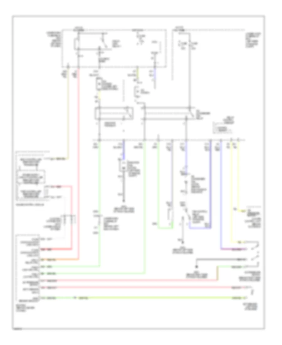
COOLING FAN
Cooling Fan Wiring Diagram for Acura TL 2006
List of elements for Cooling Fan Wiring Diagram for Acura TL 2006:
- (ect) sensor
- (sg2) sensor ground
- A/c a14
- A/c condenser fan motor (behind right side of radiator)
- A/c condenser fan relay
- A/c diode a
- A/c diode b (under left side of dash)
- A/c pressure switch
- A/c pressure switch (behind right side of front bumper)
- A13
- A14
- B-can
- B10 (fanh) high fan ctrl
- B11
- Body controller area network transceiver
- C12
- Climate control unit (behind glove box)
- Control block
- D11
- D15
- D16
- D17
- E10
- E11
- E14
- E15
- E26
- E5 (mrly) relay ctrl
- E6 (fanl) low fan ctrl
- Ecm/pcm (behind center of dash)
- Ect sensor (left side of engine)
- F-can communication line (high)
- F-can communication line (low)
- F14
- F15
- F17
- F19
- Fan control relay (left side of engine compt)
- Fast controller area network transceiver
- Fuse 23 7.5a
- Fuse 30a
- Fuse 7.5a
- G201 (behind right side of front bumper)
- G301 (behind left side of front bumper)
- Gauge control module
- Hot at all times
- Hot in on
- Input
- Junction connector c512 (under middle of dash)
- Micu
- Pgm-fi main relay 1
- Pressure switch
- Radiator fan motor (left side of engine compt)
- Radiator fan relay
- Red
- Relay control module
- Under-dash fuse/relay box (behind left end of dash)
- Under-hood fuse/relay box (left rear of engine compt)
- X11
 English