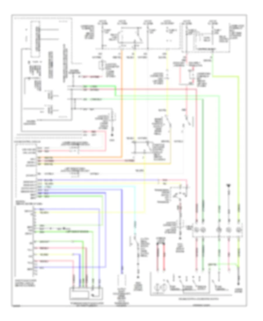
CRUISE CONTROL
Cruise Control Wiring Diagram for Acura TL 2006
List of elements for Cruise Control Wiring Diagram for Acura TL 2006:
- (left side of dash) junction connector c507
- (under middle of dash) junction connector c512
- 2004 early production
- 2005 & 2004 late prod
- A13
- A14
- A25
- A26
- A28
- A29
- A30
- B10
- B17
- B19
- Brake pedal position switch (near brake pedal)
- C10
- C19
- Cable reel
- Can high sig
- Can low sig
- Cancel switch
- Clutch pedal position switch (m/t) (near clutch pedal)
- Control block
- Control dimming circuit a/t gear position/cruise
- Cruise control combination switch
- Cruise control indicator
- Cruise control main switch indicator
- Dbw m+
- Dbw m-
- Dbwrly
- Drive circuit
- Drive input
- E15
- E26
- E30
- Ecm/pcm (behind center of dash)
- Fuse 1 15a
- Fuse 13 20a
- Fuse 18 15a
- Fuse 7 7.5a
- G101 (left side of engine)
- G501
- G503 (under middle of dash)
- Gauge control module
- Gauges/ indicators
- Horn relay
- Horns system
- Hot at all times
- Hot in on or start
- Interior lights system
- Junction connector c105 (left side of engine)
- Junction connector c507 (left side of dash)
- Junction connector c510 (under middle of dash)
- Main switch
- Mrly
- N21
- N29
- Network transceiver fast controller area
- Output shaft (countershaft) speed sensor (m/t: in transmission housing)
- Pg2
- Pgm-fi main relay 1
- Pnk
- Red
- Relay control module
- Resume switch
- Sedf
- Sefd
- Sensor input
- Set switch
- Steering wheel
- Sw input
- Switch input
- Thl1
- Thl2
- Throttle actuator control module (behind glove box)
- Throttle actuator control module relay (behind glove box)
- Tp sensor/throttle actuator (on throttle body)
- Transmission range switch (a/t) (on transaxle)
- Under-dash fuse/relay box (behind left end of dash)
- Under-hood fuse/relay box (left rear of engine compt)
- Vcc
- X23
- X28
- X35
 English