SHIFT INTERLOCK
Electric Parking Brake Wiring Diagram for Mercedes-Benz SLK250 2014

List of elements for Electric Parking Brake Wiring Diagram for Mercedes-Benz SLK250 2014:
- (left front footwell) w15/5
- 12i
- 30l
- 30r
- Can-e h
- Can-e l
- Computer data lines system
- Electric parking brake control unit (right front of trunk)
- Electric parking brake switch
- Fuse 30a
- Fuse 5a
- Hot at all times
- Hot w/ circuit 15 relay energized
- Interior lights system
- Left electric parking brake actuator motor (on left rear brake caliper assembly)
- Motor l+
- Pnk
- Rear sam control unit w/ fuse & relay module (front of trunk)
- Right electric parking brake actuator motor (on right rear brake caliper assembly)
- S89
- S90
- Sw-1
- Sw-3
- Sw-4
- Sw-6
- W7 (right side of trunk)
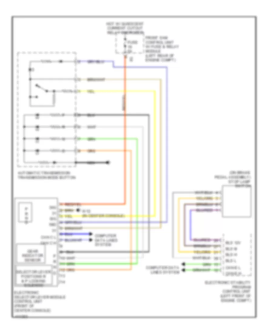
Shift Interlock Wiring Diagram for Mercedes-Benz SLK250 2014
List of elements for Shift Interlock Wiring Diagram for Mercedes-Benz SLK250 2014:
- (on brake pedal assembly) stop lamp switch
- 30g
- 58d
- Automatic transmission transmission mode button
- Bls 12v
- Bls h
- Bls l
- Bls m
- Can c h
- Can c l
- Can-e h
- Can-e l
- Computer data lines system
- Electronic selector lever module control unit (front of center console)
- Electronic stability program control unit (left front of engine compt)
- Front sam control unit w/ fuse & relay module (left rear of engine compt)
- Fuse 5a
- Gear indicator sensor
- Hot w/ quiescent current cutout relay energized
- Nca
- R n d
- Selector lever positions r & p locking solenoid
- Sig
- W12 (in center console)