AIR CONDITIONING
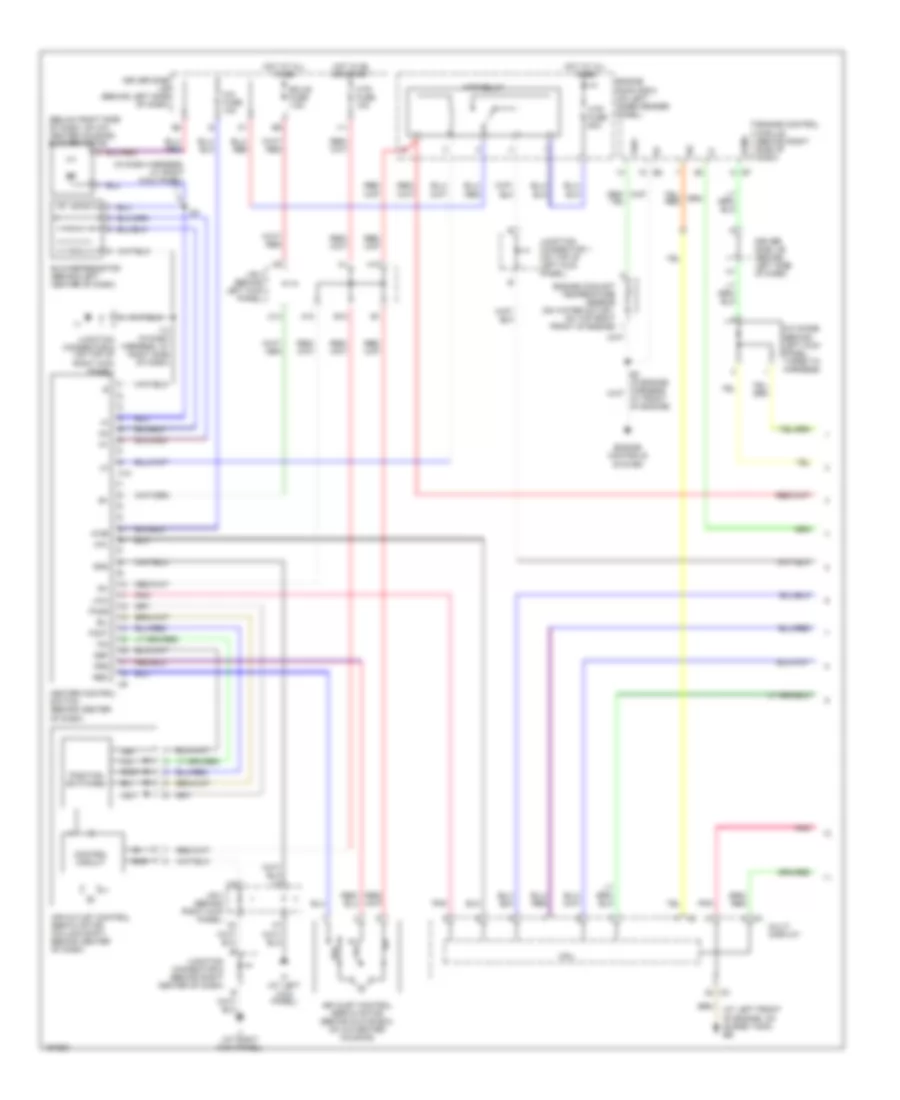
Automatic A/C Wiring Diagram (1 of 2) for Toyota Avalon XL 2004

List of elements for Automatic A/C Wiring Diagram (1 of 2) for Toyota Avalon XL 2004:
- (at left front of engine, on surge tank) eb
- (in dash harness, at right side of dash) i13
- A/c ambient temperature sensor (on lower right front of grille)
- A/c control assembly (behind center of dash)
- A/c room temperature sensor (behind left center of dash)
- A/c solar sensor (on top left side of dash)
- A/c thermistor (behind center of dash)
- A10
- A15
- A16
- A21
- A22
- Ac1
- Acin
- Aif
- Air
- Air inlet control servo motor (behind glove box, on a/c- heater housing)
- Air mix control servo motor (driver side) (behind left center of dash, on a/c-heater housing)
- Air mix control servo motor (passenger side) (behind right side of dash)
- Air outlet control servo motor (column shift: behind center of dash)
- Amdc
- Amdh
- Ampc
- Amph
- Aod
- Aof
- B21
- B22
- Blw
- C14
- C21
- Cpu
- D10
- Driver side j/b (behind left side of dash)
- Ecu-b fuse 7.5a
- Engine room r/b 5 (on left inner fender panel)
- F21
- Gnd
- H10
- Hot at all times
- Hot in on or start
- Htr fuse 10a
- Htr fuse 50a
- Htr relay
- I11
- If (at left kick panel)
- Ig+
- Ign
- Ii (at right kick panel)
- J/b 3 (behind left kick panel)
- J/b 4 (behind right kick panel)
- Junction connector 1 (on top of left kick panel)
- Lock
- Multi- display
- Pnk
- Psw
- Red
- Spd
- Tami
- Tpd
- Tpi
- Tpo
- Tpp
- Tsd
- Tsp
- Ver1
- W/ floor shift
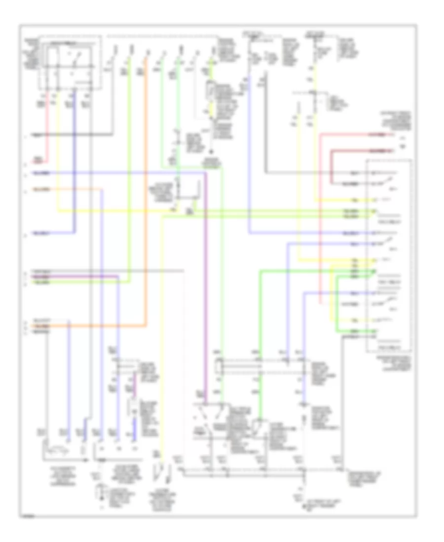
Automatic A/C Wiring Diagram (2 of 2) for Toyota Avalon XL 2004
List of elements for Automatic A/C Wiring Diagram (2 of 2) for Toyota Avalon XL 2004:
- (at front of left front fender) ed
- (on right front of engine compartment) a/c condenser fan motor
- A/c
- A/c blower motor linear controller (behind center of dash)
- A/c diode (behind left kick panel, taped to harness)
- A/c magnetic clutch & lock sensor (on a/c compressor)
- A/c triple pressure switch (a/c dual & single pressure switch) (on lower right front of engine compartment)
- Acmg
- Blower motor (below right side of dash, on a/c- heater housing)
- Cds fuse 30a
- Driver side j/b (behind left side of dash)
- Dual press
- Ecu-ig1 fuse 5a
- Engine control module (behind right side of dash) e5
- Engine controls system
- Engine coolant temperature sensor (on water outlet, on top right front of engine)
- Engine room j/b (on left front inner fender panel)
- Engine room r/b 3 (on left front of engine compartment)
- F12
- Fan 1 relay
- Fan 2 relay
- Fan 3 relay
- Gnd
- H11
- Hot at all times
- Hot in on or start
- J/b 3 (behind left kick panel)
- Junction connector 9 (on top of right kick panel)
- Mg clt relay
- Radiator fan motor (on left front of engine compartment)
- Rdi fuse 30a
- Single press
- Tach
- Thw
- Thwo
- Water temperature switch 1 (on right front of engine compartment)
- Water temperature switch 2 (on top rear of intake manifold)
Manual A/C Wiring Diagram (1 of 2) for Toyota Avalon XL 2004
List of elements for Manual A/C Wiring Diagram (1 of 2) for Toyota Avalon XL 2004:
- (at left front of engine, on surge tank) eb
- (below right side of dash, on a/c- heater housing) blower motor
- (in dash harness, at right kick panel)
- A/c
- A/c diode (behind left kick panel, taped to harness)
- A/c fuse 10a
- A/c-
- A/cb
- A10
- Acmg
- Air inlet control servo motor (behind glove box, on a/c-heater housing)
- Air outlet control servo motor (column shift: behind center of dash)
- B/l
- B10
- Blower resistor (behind left center of dash)
- C14
- Control circuit
- Cpu
- Def
- Driver side j/b (behind left side of dash)
- Ecu-b fuse 7.5a
- Engine control module (behind right side of dash)
- Engine controls system
- Engine coolant temperature sensor (on water outlet, on top right front of engine)
- Engine room r/b 5 (on left inner fender panel)
- F/d
- Face
- Foot
- Frs
- Gnd
- H10
- Heater control switch (behind center of dash)
- Hot at all times
- Hot in on or start
- Htr fuse 10a
- Htr fuse 50a
- Htr relay
- I11
- I13 (in dash harness, at right side of dash)
- I20
- If (at left kick panel)
- Ig+
- Ii (at right kick panel)
- J/b 3 (behind left kick panel)
- J/b 4 (behind right kick panel)
- Junction connector 1 (on top of left kick panel)
- Junction connector 6 (behind right center of dash)
- Junction connector 9 (on top of right kick panel)
- La/c
- Multi display
- Pnk
- Position switches
- Rec
- Thw
- Vent
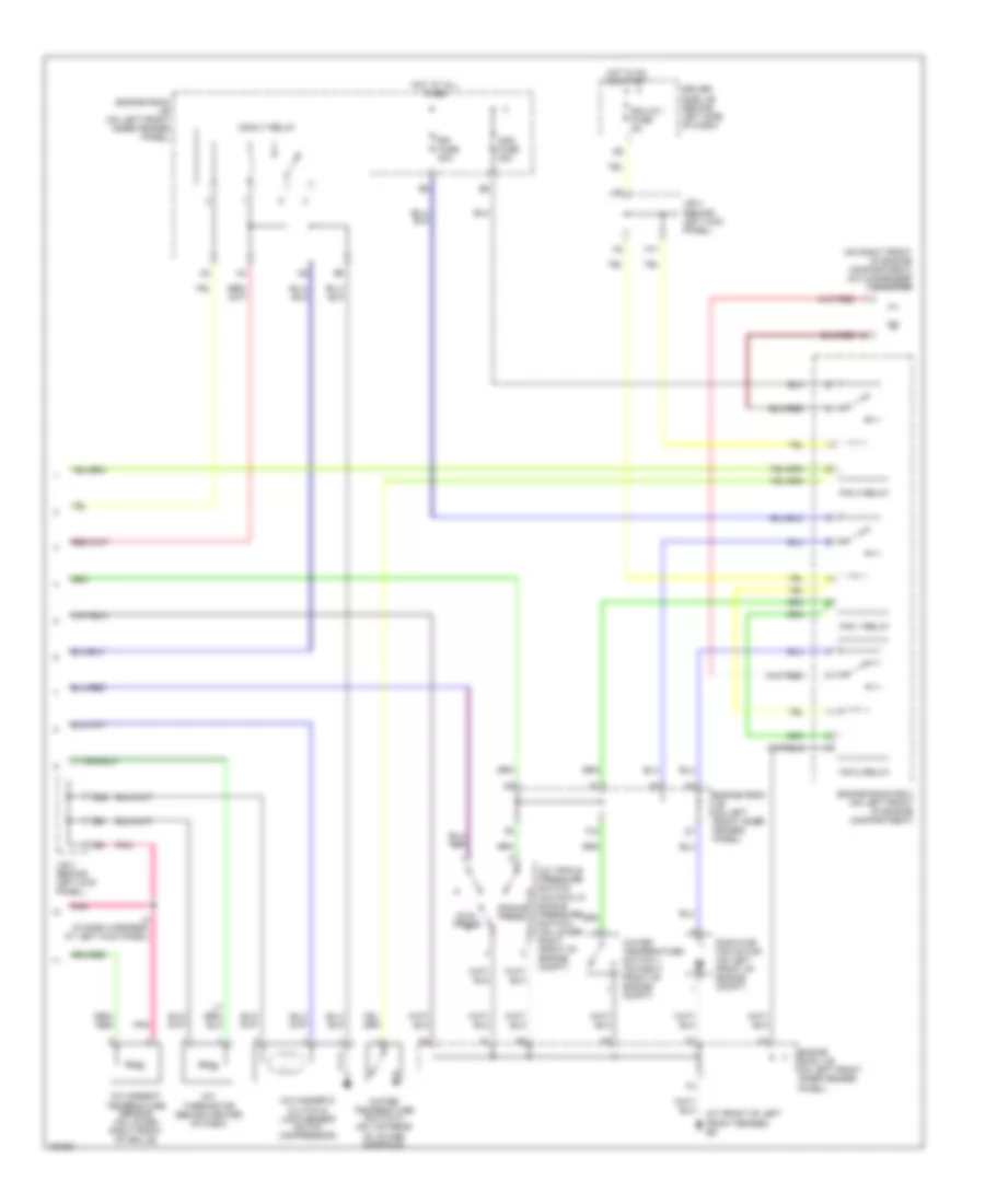
Manual A/C Wiring Diagram (2 of 2) for Toyota Avalon XL 2004
List of elements for Manual A/C Wiring Diagram (2 of 2) for Toyota Avalon XL 2004:
- (at front of left front fender) ed
- (on right front of engine compartment) a/c condenser fan motor
- A/c ambient temperature sensor (on lower right front of grille)
- A/c magnetic clutch & lock sensor (on a/c compressor)
- A/c thermistor (behind center of dash)
- A/c triple pressure switch (a/c dual & single pressure switch) (on lower right front of engine compt)
- Cds fuse 30a
- Driver side j/b (behind left side of dash)
- Dual press
- Ecu-ig 1 fuse 5a
- Engine room j/b (on left front inner fender panel)
- Engine room r/b 3 (on left front of engine compartment)
- F12
- Fan 1 relay
- Fan 2 relay
- Fan 3 relay
- G22
- H11
- Hot at all times
- Hot in on or start
- I4 (in dash harness, at left kick panel)
- J/b 3 (behind left kick panel)
- Mg/clt relay
- Pnk
- Radiator fan motor (on left front of engine compt)
- Rdi fuse 30a
- Single press
- Water temperature switch 1 (on right front of engine compt)
- Water temperature switch 2 (on top rear of intake manifold)