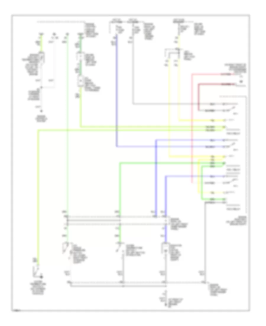
COOLING FAN
Cooling Fan Wiring Diagram for Toyota Avalon XL 2004
List of elements for Cooling Fan Wiring Diagram for Toyota Avalon XL 2004:
- (at front of left front fender) ed
- (on right front of engine compt) a/c condenser fan motor
- A/c diode (behind left kick panel, taped to harness)
- A/c single pressure switch (on lower right front of engine compt)
- Acmg
- Cds fuse 30a
- Driver side j/b (behind left side of dash)
- E2 (in engine harness, at front of engine)
- Ecu-ig 1 fuse 5a
- Engine control module (behind right side of dash) e7
- Engine controls system
- Engine coolant temperature sensor (on water outlet, on
- Engine room j/b (on left front inner fender panel)
- Engine room r/b 3 (on left front of engine compt)
- F12
- Fan 1 relay
- Fan 2 relay
- Fan 3 relay
- H11
- Hot at all times
- Hot in on or start
- J/b 3 (behind left kick panel)
- Radiator fan motor (on left front of engine compt)
- Rdi fuse 30a
- Thw
- Top right front of engine)
- Water temperature switch 1 (on left bottom of radiator)
- Water temperature switch 2 (on top rear of intake manifold)
 English