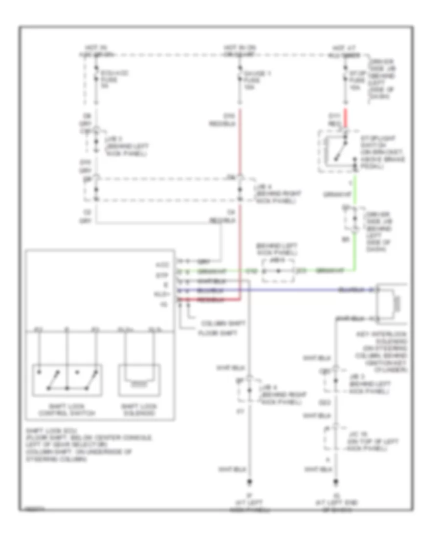
SHIFT INTERLOCK
Shift Interlock Wiring Diagram for Toyota Avalon XL 2004
List of elements for Shift Interlock Wiring Diagram for Toyota Avalon XL 2004:
- (behind left kick panel) j/b 3
- Acc
- C12
- C15
- C22
- Column shift
- D11 red
- D15
- D22
- Driver side j/b (behind left side of dash)
- Ecu-acc fuse 5a
- Floor shift
- Gauge 1 fuse 10a
- Hot at all times
- Hot in acc or on
- Hot in on or start
- If (at left kick panel)
- Ig (at left end of dash)
- J/b 3 (behind left kick panel)
- J/b 4 (behind right kick panel)
- J/c 16 (on top of left kick panel)
- Key interlock solenoid (on steering column, behind ignition key cylinder)
- Kls+
- Shift lock control switch
- Shift lock ecu (floor shift: below center console, left of gear selector) (column shift: on underside of steering column)
- Shift lock solenoid
- Sls+
- Sls-
- Stop fuse 15a
- Stoplight switch (on bracket, above brake pedal)
- Stp
 English