ANTI-LOCK BRAKES
Anti-lock Brake Wiring Diagrams for Toyota Tundra 2001
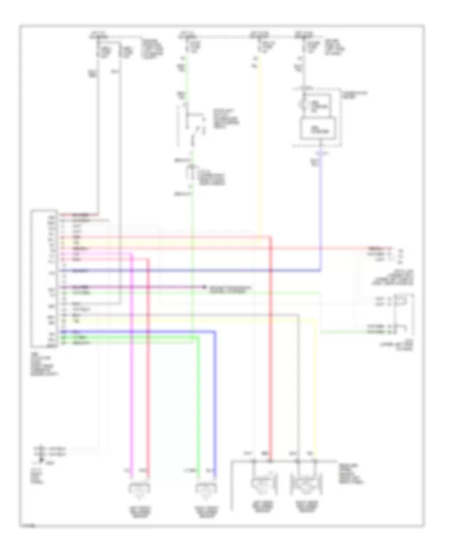
List of elements for Anti-lock Brake Wiring Diagrams for Toyota Tundra 2001:
- +bm
- +bs
- Abs 1 fuse 40a
- Abs 2 fuse 40a
- Abs actuator & ecu (right rear corner of engine compt)
- Abs inverter
- Abs warning ind
- C11
- Combination meter
- D/g
- Data link connector 3 (under left side of dash, near console)
- Driver side j/b (left side of dash)
- Ecu ig fuse 5a
- Engine room r/b (left side of engine compt)
- Engine/transmission control systems
- Exi
- Fl+
- Fl-
- Fr+
- Fr-
- G203
- Gauge fuse 10a
- Gnd
- Hot at all times
- Hot in on or start
- Ig1
- J/c 12 (upper right side of dash, near airbag)
- J/c 13 (right kick panel)
- J/c 5 (upper left side of dash)
- Left front abs speed sensor
- Left rear abs speed sensor
- Pnk
- Rear abs speed sensor (near left rear wheel)
- Red
- Right front abs speed sensor
- Right rear abs speed sensor
- Rl+
- Rl-
- Rr+
- Rr-
- Sil
- Stop fuse 15a
- Stoplight switch (on bracket above brake pedal)
- Stp
 English