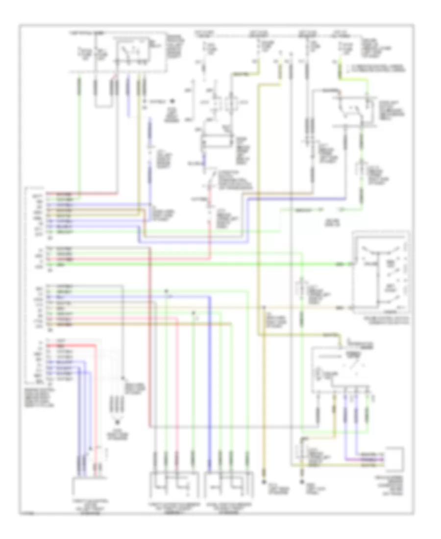
CRUISE CONTROL
3.4L
3.4L, Cruise Control Wiring Diagram for Toyota Tundra 2001

List of elements for 3.4L, Cruise Control Wiring Diagram for Toyota Tundra 2001:
- (w/a/t)
- (w/m/t)
- A/t indicator switch (park/neutral position switch
- Acc fuse 15a
- C/c
- C11
- C13
- C19
- Cancel
- Ccs
- Combination meter
- Control circuit
- Cruise
- Cruise control actuator (on right side of engine compt)
- Cruise control clutch switch
- Cruise control ecu (behind upper right center of dash)
- Cruise control ind
- Cruise control switch (combination switch)
- Data link connector 3 (under left side of dash)
- Diode (a/t) (behind upper left side of dash)
- Driver side j/b (behind lower left side of dash)
- Ect
- Ecu ig fuse 5a
- Engine control module (ecm) (behind right side of dash, near "a" pillar)
- G11
- G13
- G200 (left kick panel)
- G202
- G203
- Gauge fuse 10a
- Gnd
- Hot at all times
- Hot in acc or on
- Hot in on or start
- Idl
- Idlo
- J/c 12
- J/c 12 (behind upper right side of dash)
- J/c 13 (right kick panel)
- J/c 3 (left kick panel)
- J/c 5 (behind upper left side of dash)
- J/c 7 (behind upper left side of dash)
- J/c 8
- J/c 8 (behind upper left side of dash)
- J/c 9 (behind upper left side of dash)
- Od1
- Res/ acc
- Set/ coast
- Spd
- Stop fuse 15a
- Stoplight switch (on bracket, above brake pedal)
- Stp-
- Vehicle speed sensor (combination meter) (on trans)
4.7L
4.7L, Cruise Control Wiring Diagram for Toyota Tundra 2001
List of elements for 4.7L, Cruise Control Wiring Diagram for Toyota Tundra 2001:
- +b1
- +bm
- Acc fuse 15a
- Accel position sensor (on right front of engine)
- Batt
- C11
- C13
- Cancel
- Ccs
- Cl+
- Cl-
- Combination meter
- Cruise
- Cruise control switch (combination switch)
- Cruise ind
- D position switch (park/neutral position switch) (on transmission)
- Diode (a/t) (behind upper left side of dash)
- Driver side j/b
- Driver side j/b (behind lower left side of dash)
- E01
- E02
- E03
- E31
- Efi 1 fuse 20a
- Efi relay
- Engine control module (ecm) (behind right side of dash, near "a" pillar)
- Engine room r/b (on left side of engine compt)
- Etcs fuse 15a
- F11
- G102 (left front fender)
- G11
- G114 (left rear of engine)
- G120 (right side of engine)
- G200 (left kick panel)
- Gauge fuse 10a
- Ge01
- Hot at all times
- Hot in acc or on
- Hot in on or start
- I10 (eng harn, right side of dash)
- I5 (dash harn, right side of dash)
- I7 (eng harn, right side of dash)
- Ign fuse 5a
- Igsw
- J/c 1 (on left side of engine compt)
- J/c 12 (behind upper right side of dash)
- J/c 7 (behind upper left side of dash)
- J/c 8
- J/c 8 (behind upper left side of dash)
- J/c 9
- Me01
- Mrel
- Red
- Res/ acc
- Set/ coast
- Spd
- Speedo- meter
- St1-
- Stop fuse 15a
- Stoplight switch (on bracket, above brake pedal)
- Stp
- Throttle control motor (on left front of engine)
- Throttle position sensor (on throttle body assembly)
- Vehicle speed sensor (combination meter) (on trans)
- Vpa
- Vpa2
- Vta
- Vta2
- W/ remote control mirror w/o remote control mirror