
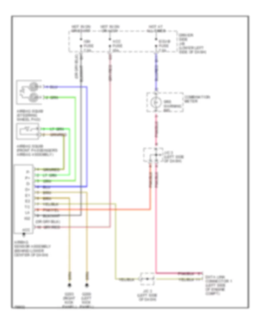
SUPPLEMENTAL RESTRAINTS
Supplemental Restraint Wiring Diagram for Toyota 4Runner SR5 1998
List of elements for Supplemental Restraint Wiring Diagram for Toyota 4Runner SR5 1998:
ANTI-LOCK BRAKESENGINE PERFORMANCEAIR CONDITIONINGCOMPUTER DATA LINESCRUISE CONTROLEXTERIOR LIGHTSINSTRUMENT CLUSTERDEFOGGERSHORNGROUND DISTRIBUTIONPOWER DOOR LOCKSINTERIOR LIGHTSPOWER ANTENNAPOWER MIRRORSHEADLIGHTSPOWER TOP/SUNROOFPOWER DISTRIBUTIONPOWER SEATSSHIFT INTERLOCKSPOWER WINDOWSTRANSMISSIONSUPPLEMENTAL RESTRAINTSRADIOSTARTING/CHARGINGWARNING SYSTEMSWIPER/WASHER