TRANSMISSION
4WD Wiring Diagram, with 2-4 Select Switch for Toyota 4Runner SR5 1998

List of elements for 4WD Wiring Diagram, with 2-4 Select Switch for Toyota 4Runner SR5 1998:
- (dash harn, left kick panel) i1
- 2-4
- 2-4 select motor (on transfer case)
- 2-4 select switch
- 2wd
- 4wd
- 4wd ecu (left kick panel)
- 4wd fuse 20a
- 4wd indicator
- A/t
- A/t ind switch
- A/t parking indicator
- A17
- Abs ecu (right kick panel)
- Add indicator switch (middle of engine compt)
- C10
- C11
- C12
- C16
- C19
- Center j/b (right of steering column)
- Detection switch (transfer 4wd position) (transfer case)
- Detection switch (transfer l4 position) (transfer case)
- Detection switch (transfer neutral position) (transfer case)
- Diff lock ecu (left kick panel)
- Driver side j/b (lower left side of dash)
- E11
- E16
- E18
- Engine control module (behind right side of dash)
- Exi
- Exi3
- G100 (front of left front fender)
- G201 (right side of dash)
- Gauge fuse 10a
- Gnd
- Hot in on or start
- I11
- I11 (dash harn, right side of dash)
- I11 (dash harness, upper right side of dash)
- I5 (dash harness, upper left side of dash)
- Ind
- Instrument cluster
- J/c 1 (left front of engine compt)
- J/c 2
- J/c 7
- J/c 8 (upper right side of dash)
- J/c 9
- Park/ neutral position switch
- Pnk
- Rl1
- Rl2
- Spd
- Speedometer
- Tfn
- Vsv (2wd, add) (left side of engine compt)
- Vsv (4wd, add) (left side of engine compt)
- W/ rear diff lock
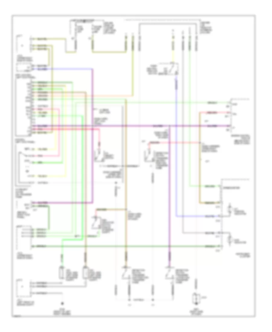
4WD Wiring Diagram, without 2-4 Select Switch for Toyota 4Runner SR5 1998
List of elements for 4WD Wiring Diagram, without 2-4 Select Switch for Toyota 4Runner SR5 1998:
- (dash harn, right side of dash)
- (dash harn, upper right side of dash)
- (right kick panel)
- (transfer case)
- (upper right side of dash)
- 2.7l
- 3.4l
- 4wd
- 4wd fuse 20a
- 4wd ind
- A/t
- A/t parking ind
- Abs ecu
- Add control relay (behind right side of dash)
- Add indicator switch (middle of engine compt)
- C10
- C11
- C19
- Center j/b (right of steering column)
- Combination meter
- Dash harn, upper right side of dash)
- Dectection switch (transfer 4wd pos) (transfer case)
- Dectection switch (transfer l4 pos) (transfer case)
- Detection switch (transfer neutral position)
- Diff lock ecu (left kick panel)
- Driver side j/b (lower left side of dash)
- E11
- E16
- E18
- Engine control module (behind right side of dash)
- Exi
- Exi3
- G100 (front of left front fender)
- G201 (right side of dash)
- Gauge fuse 10a
- Hot in on or start
- I10 or i11
- I11
- I19
- J/c 2 (left front of engine compt) j/c 1
- J/c 7
- J/c 7 (upper right side of dash) j/c 8
- J/c 8
- J/c 9
- Nca
- Park/neutral position switch (a/t indicator switch) (transmission)
- Short pin (w/o add)
- Tfn
- Vsv (2wd, add) (left side of engine compt)
- Vsv (4wd, add) (left side of engine compt)
- W/ add
- W/ add only
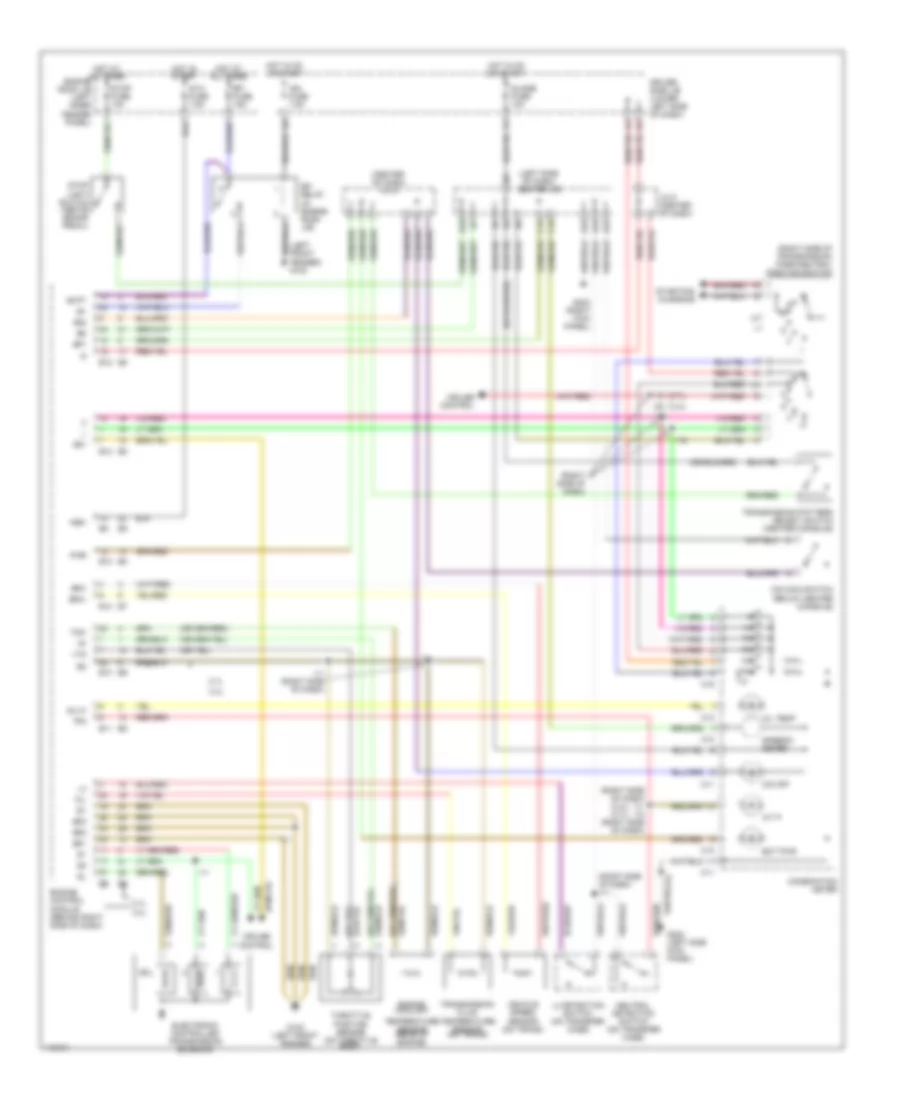
A/T Wiring Diagram for Toyota 4Runner SR5 1998
List of elements for A/T Wiring Diagram for Toyota 4Runner SR5 1998:
- (2.7l)
- (3.4l)
- (3.4l) (2.7l)
- (center of dash) j/c 6
- (left front fender) g100
- (left side of dash) center j/b
- (right side of dash)
- (right side of dash) i11
- (right side of dash) i11 i10 (right side of dash)
- (right side of transmission) park/neutral position switch
- 2.7l
- 3.4l
- A/t p
- Batt
- C10
- C11
- C12
- C15
- C16
- C19
- Combination meter
- Cruise control
- Driver side j/b (lower left side of dash)
- E10
- E11
- E12
- E16
- E18
- E22
- Ect pwr
- Efi
- Efi fuse 15a
- Electronic controlled transmission solenoid
- Engine control module (behind right side of dash)
- Engine coolant
- Engine romm j/b (left inner fender panel)
- Eo1
- Eo2
- Eo3
- G100 (left front fender)
- G202 (left side kick panel)
- G203 (right kick panel)
- Guage fuse 10a
- Hot at all times
- Hot in on or start
- Hot in start
- I10
- I11
- I11 (right side of dash)
- I19
- I20
- Ign fuse 7.5a
- J/c 5 (center of dash)
- L4 detection switch (on transfer case)
- Neutral detection switch (on transfer case)
- Nsw
- O/d main switch (below center console)
- O/d off
- Od1
- Od2
- Oil
- Oil temp
- Oil-w
- Pwr
- Relay (in engine room j/b)
- Sol
- Sp1
- Sp2+
- Sp2-
- Speedo- meter
- Sta fuse 7.5a
- Starting/ charging
- Stop fuse 10a
- Stop light switch (above brake pedal)
- Temperature sensor (rear of engine)
- Tfn
- Throttle position sensor (on throttle body)
- Thw
- Transmission fluid temperature sensor (on trans)
- Transmission pattern select switch (center console)
- Vehicle speed sensor (on trans)
- Vta
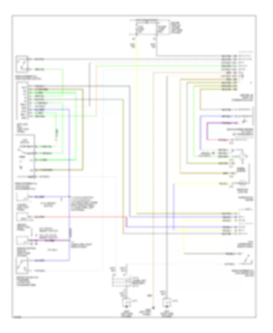
Rear Differential Lock Wiring Diagram for Toyota 4Runner SR5 1998
List of elements for Rear Differential Lock Wiring Diagram for Toyota 4Runner SR5 1998:
- (under left rear seat) j/c 12
- 2.7l w/o 2-4 select switch
- 3.4l, 2.7l w/ 2-4 select switch
- 4wd
- 4wd ecu (left kick panel)
- 4wd fuse 20a
- A/t only
- A17
- Abs ecu (3.4l only)
- Abs ecu (right kick panel)
- C10
- C11
- C12
- C14
- C16
- Center j/b (right of steering column)
- Combination meter
- Detection switch (transfer l4 position) (transfer case)
- Diff lock ecu (left kick panel)
- Driver side j/b (lower left side of dash)
- E14
- E16
- E18
- Engine control module (right side of dash)
- Exi2
- Free
- G200 (left kick panel)
- G201 (right side of dash)
- G202 (left side of dash)
- Gauge fuse 10a
- Gnd
- Hot in on or start
- I11 (dash harn, right side of dash)
- I11 (w/o 2-4 switch) i1 (w/ 2-4 switch) (i10: dash harn, upper right side of dash) (i1: dash harn, left kick panel)
- J/c 13
- J/c 4
- J/c 7
- J/c 8 (upper right side of dash)
- J/c 9
- Limit switch
- Lock
- Rear diff lock ind
- Rear differential lock control switch
- Rear differential lock detection switch
- Rear differential lock motor (on differential)
- Rel1
- Rel2
- Rlp
- Rly1
- Rly2
- Spd
- Speed- ometer
- Vehicle speed sensor (2.7l only) (on transmission)
- W/ 2-4 select switch
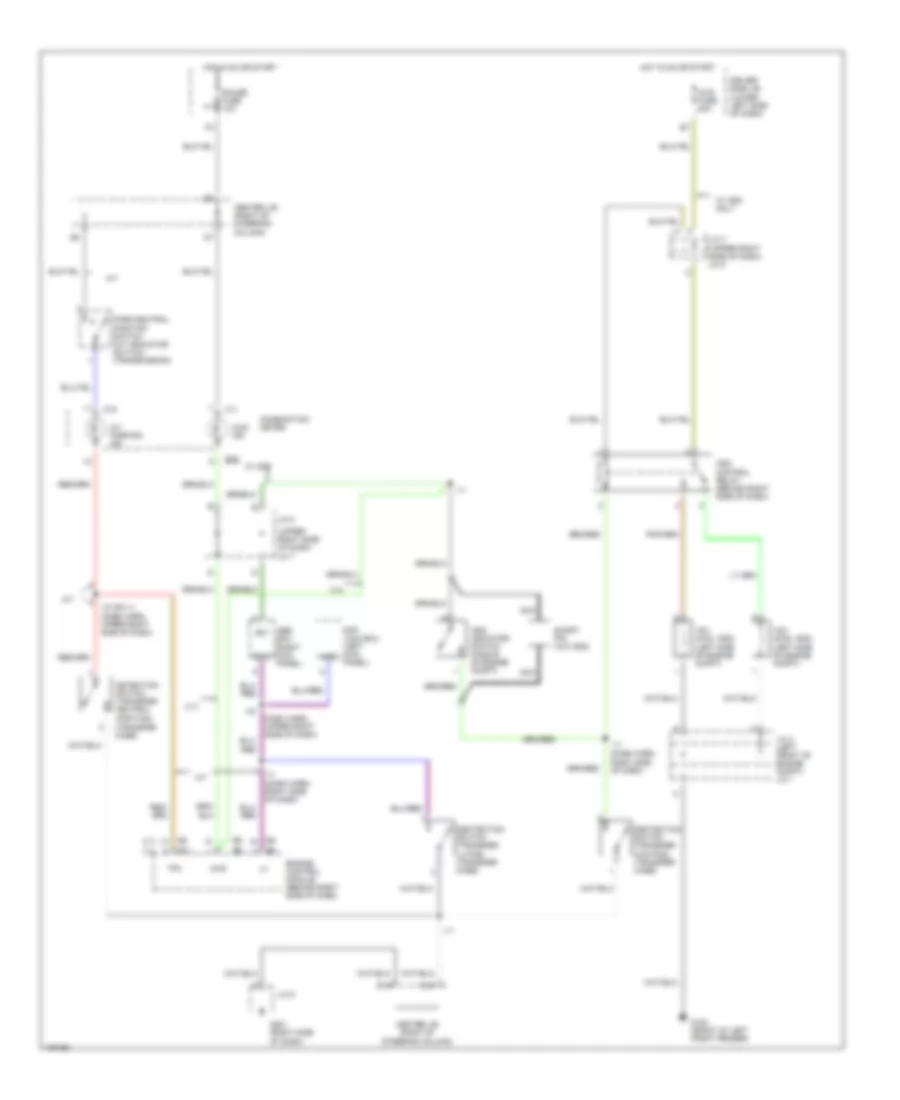
Transfer Case Wiring Diagram, with 2-4 Select Switch for Toyota 4Runner SR5 1998
List of elements for Transfer Case Wiring Diagram, with 2-4 Select Switch for Toyota 4Runner SR5 1998:
- (dash harn, left kick panel) i1
- 2-4
- 2-4 select motor (on transfer case)
- 2-4 select switch
- 2wd
- 4wd
- 4wd ecu (left kick panel)
- 4wd fuse 20a
- 4wd indicator
- A/t
- A/t ind switch
- A/t parking indicator
- A17
- Abs ecu (right kick panel)
- Add indicator switch (middle of engine compt)
- C10
- C11
- C12
- C16
- C19
- Center j/b (right of steering column)
- Detection switch (transfer 4wd position) (transfer case)
- Detection switch (transfer l4 position) (transfer case)
- Detection switch (transfer neutral position) (transfer case)
- Diff lock ecu (left kick panel)
- Driver side j/b (lower left side of dash)
- E11
- E16
- E18
- Engine control module (behind right side of dash)
- Exi
- Exi3
- G100 (front of left front fender)
- G201 (right side of dash)
- Gauge fuse 10a
- Gnd
- Hot in on or start
- I11
- I11 (dash harn, right side of dash)
- I11 (dash harness, upper right side of dash)
- I5 (dash harness, upper left side of dash)
- Ind
- Instrument cluster
- J/c 1 (left front of engine compt)
- J/c 2
- J/c 7
- J/c 8 (upper right side of dash)
- J/c 9
- Park/ neutral position switch
- Pnk
- Rl1
- Rl2
- Spd
- Speedometer
- Tfn
- Vsv (2wd, add) (left side of engine compt)
- Vsv (4wd, add) (left side of engine compt)
- W/ rear diff lock
Transfer Case Wiring Diagram, without 2-4 Select Switch for Toyota 4Runner SR5 1998
List of elements for Transfer Case Wiring Diagram, without 2-4 Select Switch for Toyota 4Runner SR5 1998:
- (dash harn, right side of dash)
- (dash harn, upper right side of dash)
- (right kick panel)
- (transfer case)
- (upper right side of dash)
- 2.7l
- 3.4l
- 4wd
- 4wd fuse 20a
- 4wd ind
- A/t
- A/t parking ind
- Abs ecu
- Add control relay (behind right side of dash)
- Add indicator switch (middle of engine compt)
- C10
- C11
- C19
- Center j/b (right of steering column)
- Combination meter
- Dash harn, upper right side of dash)
- Dectection switch (transfer 4wd pos) (transfer case)
- Dectection switch (transfer l4 pos) (transfer case)
- Detection switch (transfer neutral position)
- Diff lock ecu (left kick panel)
- Driver side j/b (lower left side of dash)
- E11
- E16
- E18
- Engine control module (behind right side of dash)
- Exi
- Exi3
- G100 (front of left front fender)
- G201 (right side of dash)
- Gauge fuse 10a
- Hot in on or start
- I10 or i11
- I11
- I19
- J/c 2 (left front of engine compt) j/c 1
- J/c 7
- J/c 7 (upper right side of dash) j/c 8
- J/c 8
- J/c 9
- Nca
- Park/neutral position switch (a/t indicator switch) (transmission)
- Short pin (w/o add)
- Tfn
- Vsv (2wd, add) (left side of engine compt)
- Vsv (4wd, add) (left side of engine compt)
- W/ add
- W/ add only