ELECTRONIC SUSPENSION
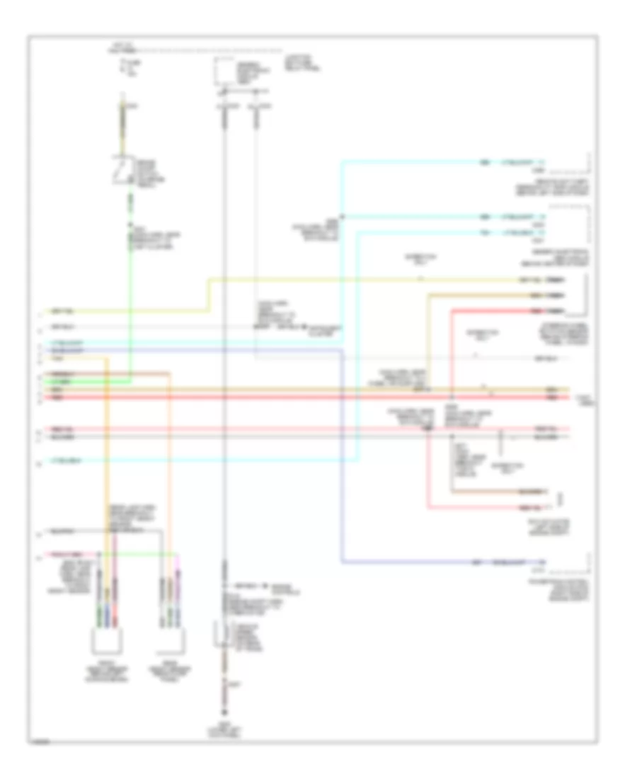
Electronic Suspension Wiring Diagram (1 of 2) for Ford Expedition 1998
 https://portal-diagnostov.com/license.html
Automotive Electricians Portal FZCO
Automotive Electricians Portal FZCO
https://portal-diagnostov.com/license.html
https://portal-diagnostov.com/license.html
Automotive Electricians Portal FZCO
Automotive Electricians Portal FZCO
List of elements for Electronic Suspension Wiring Diagram (1 of 2) for Ford Expedition 1998:
- (main harn, near breakout to 4was module) s272
- 4x4 low sig
- Air suspension compressor motor and vent solenoid (right radiator support)
- Air suspension compressor relay (near right headlamp)
- Air suspension indicator
- Air suspension service switch (behind right side of dash)
- Air suspension/ evo steering module (behind center of dash)
- All wheel drv
- Brake on/off sw
- C237
- C242
- C243
- C295
- C296
- Comp mtr vent sol
- Compressor relay
- Data link connector (under center of dash)
- Datalink
- Door ajar in
- Evo module
- Front air fill solenoid
- Front fill sol
- Front gate sol
- Front gate solenoid
- Front height sen
- Fuse 15a
- Fuse 50a
- Fuse 5a
- G108 (left front radiator suport)
- G109 (right front radiator suport)
- G109 (right front radiator support)
- G200 (lower left kick panel)
- G203 (lower right kick panel)
- Ground
- Height sen power
- Hot at all times
- Hot in run
- Hot in start
- Instrument cluster
- Junction box fuse/ relay panel
- Left rear air spring solenoid
- Lr spring sol
- Memory systems
- Pcm accel sig
- Pnk
- Power (hot in run)
- Power (start)
- Power distribution box
- Rear air fill solenoid
- Rear fill sol
- Rear height sen
- Red
- Right rear air spring solenoid
- Rr spring sol
- S104
- S155
- S177
- S210
- S229 (main harn, near breakout to evo module)
- S265
- S400
- Service switch
- Solid state
- Steering sensor
- Tan
- Transmission controls
- Vehicl speed (+)
- Warning indicator
Electronic Suspension Wiring Diagram (2 of 2) for Ford Expedition 1998
List of elements for Electronic Suspension Wiring Diagram (2 of 2) for Ford Expedition 1998:
- (main harn, near breakout to 4 wheel air susp mod) s270
- (main harn, near breakout to evo module) s267
- (main harn, near breakout to evo module) s273
- (not used)
- (rear lamp harn, near breakout to front height sensor)
- (rear lamp harn, near breakout to front height sensor) s410 or s310
- Brake on/off switch (on brake pedal)
- Breakout to inst cluster)
- C174
- C240
- C241
- C256
- Engine controls
- Evo actuator (left side of engine compt)
- Expedition only
- Front height sensor (behind left running board)
- Fuse 15a
- G200 (lower left kick panel)
- Generic electronic (gem) module (behind center of dash)
- Generic electronic module (gem)
- Hot at all times
- Instrument cluster
- Junction box fuse/ relay panel
- Nca
- Powertrain control module (pcm) (right side of engine compt)
- Rear height sensor (rear floor panel)
- Red
- Remote anti-theft personality (rap) module (behind left side of dash)
- S207
- S268 (main harn, near breakout to evo module)
- S269 (main harn, near breakout to evo module)
- S271 (main harn, near breakout to evo module)
- S409 or s311
- Steering wheel rotation sensor (behind steering wheel, in dash)
- Tan
- Vehicle speed sensor (on rear of trans)

 Čeština
 Dansk
Dansk Deutsch
 Ελληνικά
 English
 English
 Suomi
Suomi Français
 Français
 עברית
עברית Hrvatski
 Magyar
 Italiano
 日本語
日本語 한국어
한국어 Nederlands
 Polski
 Português
 Português
 Română
 Русский
 Slovenčina
 Slovenščina
 Svenska
 Türkçe
 中文 (中国)