TRANSMISSION
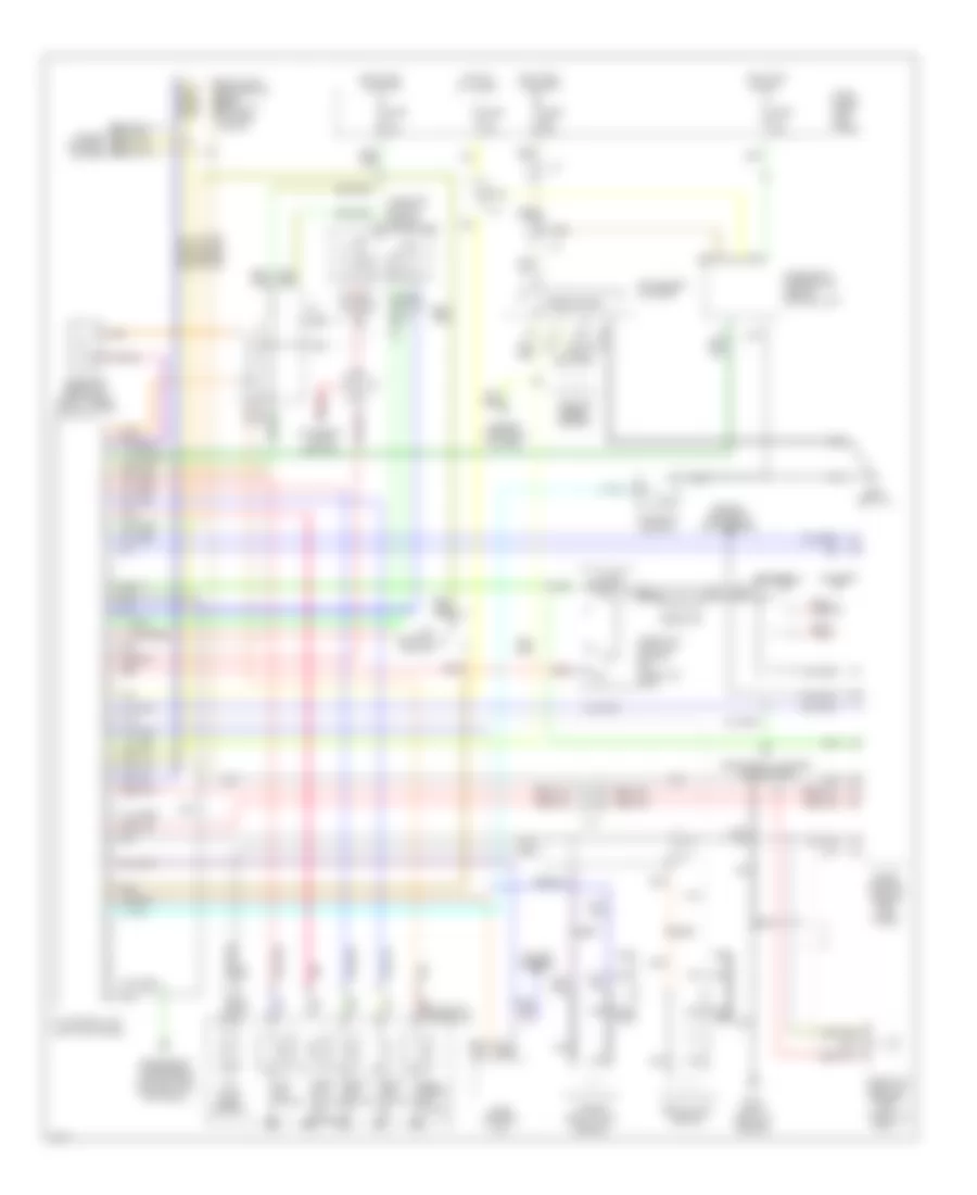
Transmission Wiring Diagram for Infiniti Q45 1994
List of elements for Transmission Wiring Diagram for Infiniti Q45 1994:
- (left kick panel)
- (right front of engine)
- 1-2
- 1st position switch
- A/t control unit
- A/t fluid temp. sensor
- All times
- Ascd control unit
- Automatic transaxle
- Battery
- Closed throttle
- Cruise control
- Cruise control system
- Data link connector (for consult) (in fuse block)
- Diagnostic information display control unit
- Dropping resistor (right front shock tower)
- Eccs control module (right kick panel)
- Eccs relay
- Electronic suspension (active susp control unit) (optional)
- Engine controls (maf sensor)
- Engine controls system
- Exterior lights (backup)
- Fuse 10a
- Fuse block (left kick panel)
- G119
- G200 (left i/p)
- Hot at
- Hot in on or acc
- Hot in on or start
- Inhibitor switch (side of transaxle)
- Instrument cluster
- Instrument cluster (tachometer)
- J/c
- Kickdown switch
- Line press. sol. valve
- Nca
- Over- run clutch sol. valve
- Pnk
- Red
- Resistor
- Revolution sensor
- Sensor
- Shift sol. valve a
- Shift sol. valve b
- Speedometer
- Tcc sol. valve
- Throttle position sensor (on throttle body)
- Throttle position switch (on throttle body)
- Turbine revolution
- Vehicle speed sensor
- Wot
 Čeština
 Dansk
Dansk Deutsch
 Ελληνικά
 English
 English
 Español
 Français
 Français
 עברית
עברית Hrvatski
 Magyar
 Italiano
 日本語
日本語 한국어
한국어 Nederlands
 Polski
 Português
 Português
 Română
 Русский
 Slovenčina
 Slovenščina
 Svenska
 Türkçe
 中文 (中国)
 Suomi
Suomi