BODY CONTROL MODULES
Comfort System Central Control Module Wiring Diagram for Audi Q5 2010
 https://portal-diagnostov.com/license.html
Automotive Electricians Portal FZCO
Automotive Electricians Portal FZCO
https://portal-diagnostov.com/license.html
https://portal-diagnostov.com/license.html
Automotive Electricians Portal FZCO
Automotive Electricians Portal FZCO
List of elements for Comfort System Central Control Module Wiring Diagram for Audi Q5 2010:
- 10a
- 11a
- Anti-theft system
- Comfort system central control module (left side of trunk)
- Computer data lines system
- Cruise control system
- Defogger system
- Door locks system
- Engine controls system
- Exterior lights system
- Fuse 20a
- Fuse 30a
- Fuse carrier 2
- G51 (behind right "d" pillar)
- Hot at all times
- Interior lights system
- Nca
- Power distribution system
- Relay/fuse panel sf (right side of luggage compt)
- Shift interlock system
- T17o
- T17p
- T32c
- T32d
- T32e
- Transmissions system
- Trunk, tailgate, fuel doors system
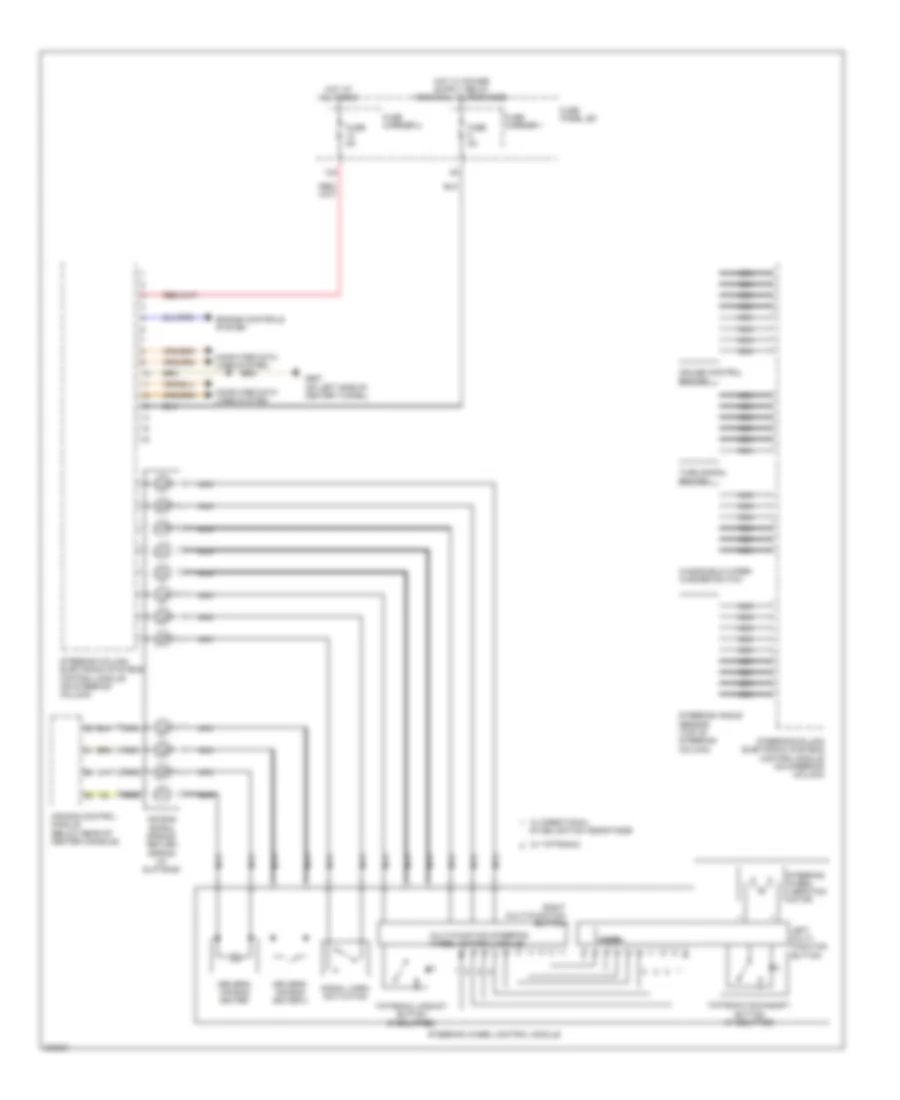
Steering Column Electronic Systems Control Module Wiring Diagram for Audi Q5 2010
List of elements for Steering Column Electronic Systems Control Module Wiring Diagram for Audi Q5 2010:
- 12a
- Air bag control module (below rear of center console)
- Air bag spiral spring/ return spring (w/ slip ring)
- Computer data lines system
- Cruise control switch
- Driver's air bag igniter
- Driver's air bag igniter 2
- Engine controls system
- Fuse 5a
- Fuse carrier 1
- Fuse carrier 2
- Fuse panel sd
- G687 (on left side of center tunnel)
- Hot at all times
- Left multi- function button
- Mode
- Multi-function steering wheel control module
- Nca
- Right multi-function button
- Signal horn activation
- Steering angle sensor (top of steering column)
- Steering column electronic systems control module (on steering column)
- Steering wheel control module
- Steering wheel vibration motor
- Tiptronic downshift button (if equipped)
- Tiptronic upshift button (if equipped)
- Turn signal switch
- W/ directional stabilization assistance
- W/ tiptronic
- Windshield wiper/ washer switch
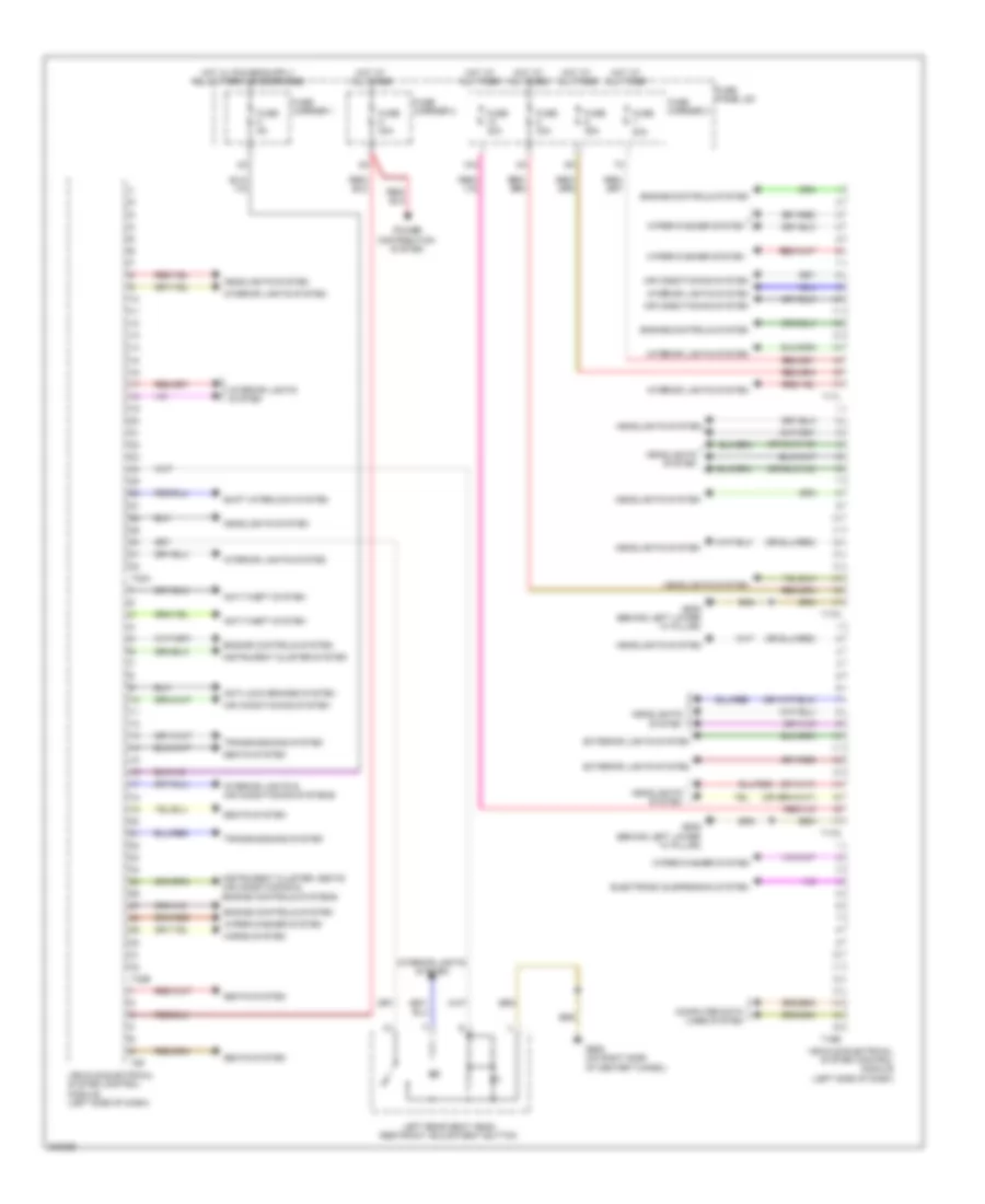
Vehicle Electrical System Control Module Wiring Diagram for Audi Q5 2010
List of elements for Vehicle Electrical System Control Module Wiring Diagram for Audi Q5 2010:
- 10a
- Air conditioning system
- Anti-lock brakes system
- Anti-theft system
- Computer data lines system
- Electronic suspension system
- Engine controls system
- Exterior lights system
- Fuse 20a
- Fuse 30a
- Fuse 35a
- Fuse 5a
- Fuse carrier 1
- Fuse carrier 2
- Fuse carrier 3
- Fuse panel sc
- G639 (behind left lower "a" pillar)
- G688 (on right side of center tunnel)
- Headlights system
- Horns system
- Hot at all times
- Instrument cluster system
- Instrument cluster, seats air conditioning & engine controls systems
- Interior lights & air conditioning systems
- Interior lights system
- Left rear seat head restraint adjustment button
- Power distribution system
- Seats system
- Shift interlock system
- T16b
- T17l
- T17m
- T17n
- T32a
- T32b
- T6f
- Transmissions system
- Vehicle electrical system control module (left side of dash)
- Wiper/washer system

 Čeština
 Dansk
Dansk Deutsch
 Ελληνικά
 English
 English
 Español
 Suomi
Suomi Français
 עברית
עברית Hrvatski
 Magyar
 Italiano
 日本語
日本語 한국어
한국어 Nederlands
 Polski
 Português
 Português
 Română
 Русский
 Slovenčina
 Slovenščina
 Svenska
 Türkçe
 中文 (中国)