SUPPLEMENTAL RESTRAINTS
Supplemental Restraint Wiring Diagram for Pontiac Firebird Trans Am 1995
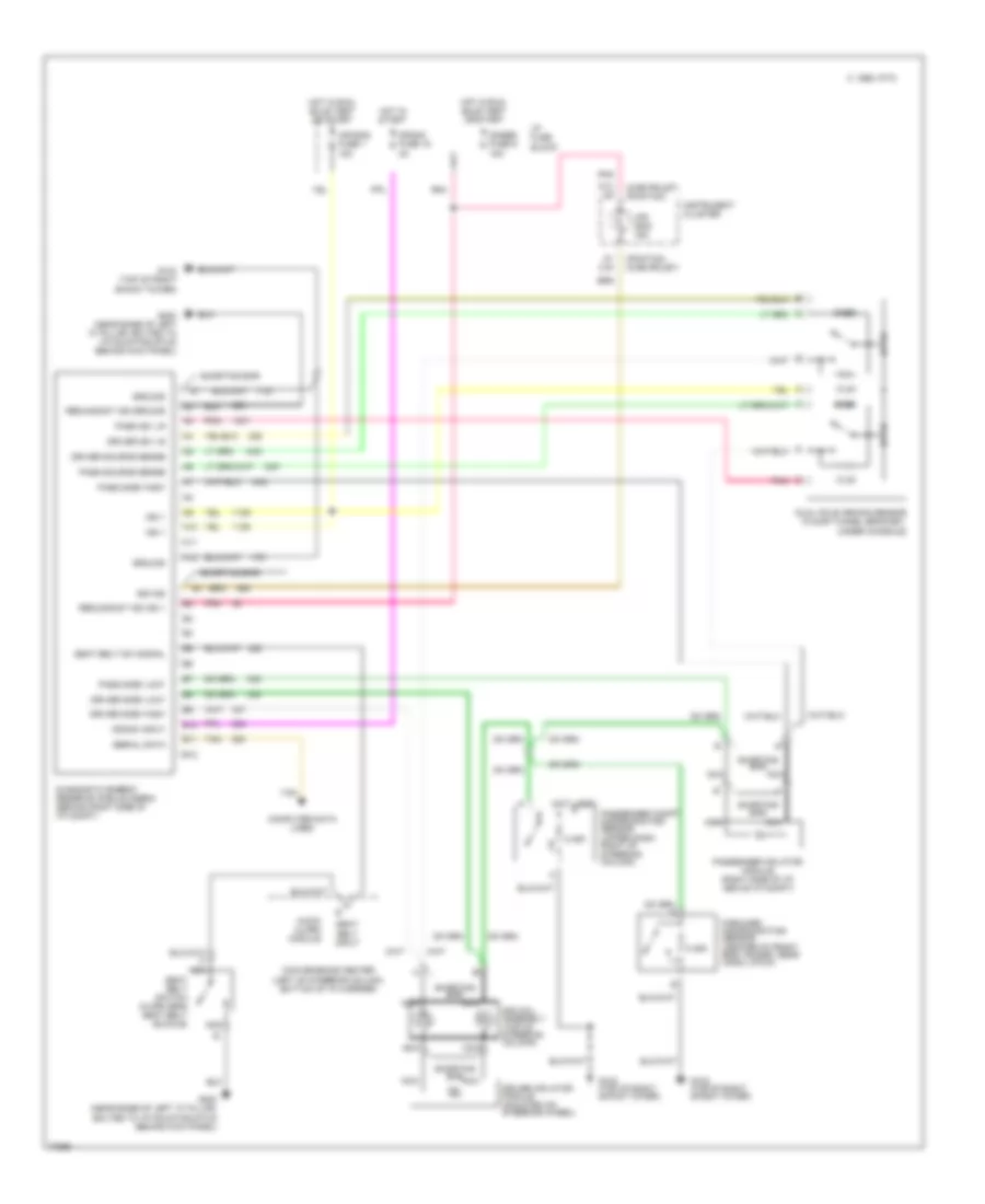
List of elements for Supplemental Restraint Wiring Diagram for Pontiac Firebird Trans Am 1995:
- (chevrolet) (pontiac)
- (not used)
- (pontiac) (chevrolet)
- 10.2k
- 2.49k
- 8.45k
- A10
- A11
- A12
- A7 c16
- Air bag fuse 1 15a
- Air bag ind
- Audio alarm module
- B10
- B11
- B12
- C 1995 vftc
- Computer data lines
- Convenience center (left of steering column, bottom of i/p carrier)
- Crank fuse 16 3a
- Crank input
- D13 a5
- Diagnostic energy reserve module (derm) (behind right side of i/p compt)
- Driver 36v lr
- Driver inflator module (mounted on steering wheel)
- Driver side "high"
- Driver side "low"
- Driver source sense
- Dual pole arming sensor (floor tunnel bracket, under console)
- Forward discriminating sensor (center of front end tie bar, near hood latch)
- G103 (top of right shock tower)
- G200 (near base of left "a" pillar, bolted to i/p mounting stud behind kick panel)
- Gages fuse 9 15a
- Ground
- Hot in run, bulb test or start
- Hot in start
- I/p fuse block
- Ign 1
- Instrument cluster
- Nca
- Pass 36v lr
- Pass side "high"
- Pass side "low"
- Pass source sense
- Passenger compt discriminating sensor (upper dash, right of steering column)
- Passenger inflator module (right side of i/p, above i/p compt)
- Pnk
- Redundant ind ground
- Redundant ind ign 1
- Seat belt input
- Seat belt sw signal
- Seat belt switch (in driver's seat belt buckle)
- Serial data
- Shorting bar
- Sir coil assembly (top of steering column)
- Sir ind
- Tan
 Čeština
 Dansk
Dansk Deutsch
 Ελληνικά
 English
 English
 Español
 Suomi
Suomi Français
 עברית
עברית Hrvatski
 Magyar
 Italiano
 日本語
日本語 한국어
한국어 Nederlands
 Polski
 Português
 Português
 Română
 Русский
 Slovenčina
 Slovenščina
 Svenska
 Türkçe
 中文 (中国)
 Français