POWER DISTRIBUTION
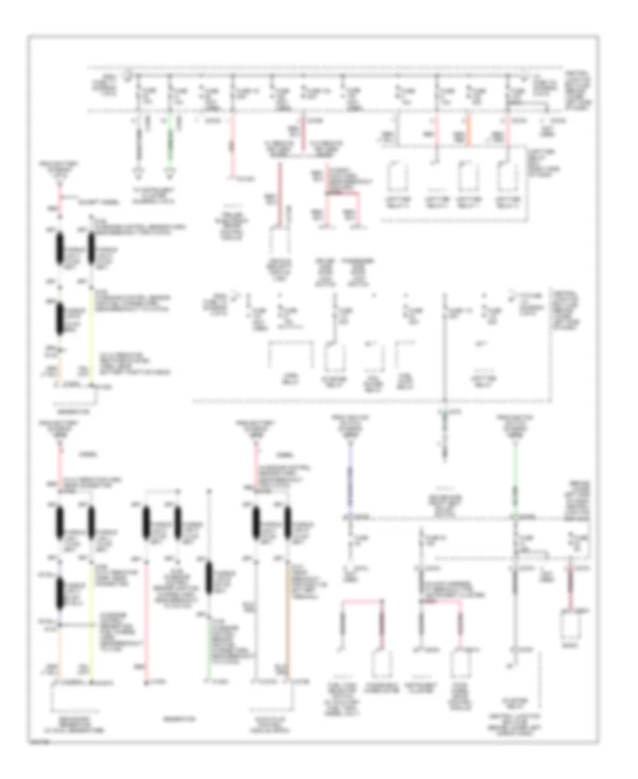
Power Distribution Wiring Diagram (1 of 5) for Ford Cab & Chassis F350 Super Duty 2005
 https://portal-diagnostov.com/license.html
Automotive Electricians Portal FZCO
Automotive Electricians Portal FZCO
https://portal-diagnostov.com/license.html
https://portal-diagnostov.com/license.html
Automotive Electricians Portal FZCO
Automotive Electricians Portal FZCO
List of elements for Power Distribution Wiring Diagram (1 of 5) for Ford Cab & Chassis F350 Super Duty 2005:
- (behind lower left side of dash) central junction box (cjb)
- (in main harn, near breakout to instrument cluster) (w/ eatc) s208
- (in main harness, near breakout for auxiliary relay box 1) s249
- (in main harness, near breakout for data link connector) s242
- (in main harness, near breakout for restraints control module) (w/ electronic shift on the fly) s230
- (in main harness, near breakout to brake pedal position switch) s214
- (not used)
- (w/ power equipment
- 2 of 5)
- 30a
- Adjustable pedal switch (w/o memory)
- Auxiliary a/c relay
- Auxiliary relay box 1 (behind left center of dash)
- Battery
- Battery ii (diesel)
- Brake pedal position switch
- C197b
- C202a
- C205a
- C2113b
- C2142b
- C218a
- C220b
- C228b
- C270a
- C270b
- C270d
- C270e
- C270g
- C270h
- C270i
- C270j
- C270k
- C290a
- Central junction box (cjb) (behind lower left side of dash)
- Data link connector (dlc)
- Driver side front heated seat relay
- Electronic automatic temperature control (eatc) module
- Exterior rear view mirror switch
- Four-wheel drive control module (w/ electronic shift on the fly)
- From a fuse 10 (diagram 1 of 5)
- From b fuse 16 (diagram 1 of 5)
- Front cigar lighter
- Fuse
- Fuse (not used)
- Fuse 1 15a
- Fuse 108 40a
- Fuse 11 20a
- Fuse 111 (not used)
- Fuse 12 20a
- Fuse 13 5a
- Fuse 17 15a
- Fuse 18 20a
- Fuse 19 10a
- Fuse 2 10a
- Fuse 20 10a
- Fuse 21 20a
- Fuse 34 10a
- Fuse 4 20a
- Fuse 6
- Fuse 7 30a
- G201 (behind left side of dash)
- Indicator flasher relay
- Instru- ment panel power point
- Instrument cluster
- Main light switch
- Multi- function switch
- Nca
- Passenger side front seat adjust switch
- Pnk
- Radio
- Red
- S1000 (in engine control sensor harn, near breakout to c1100a) red
- S1002 (in engine control sensor harn, near c1100a)
- S290
- Starter motor
- To fuse (diagram 2 of 5)
- To fuse 1 (diagram 5 of 5)
- To fuse 108 (diagram 1 of 5)
- To fuse 12 (diagram 1 of 5)
- To fusible links (diagram
- To fusible links (diagram 2 of 5)
- Trailer electronic brake control module
- Vehicle security module (vsm)
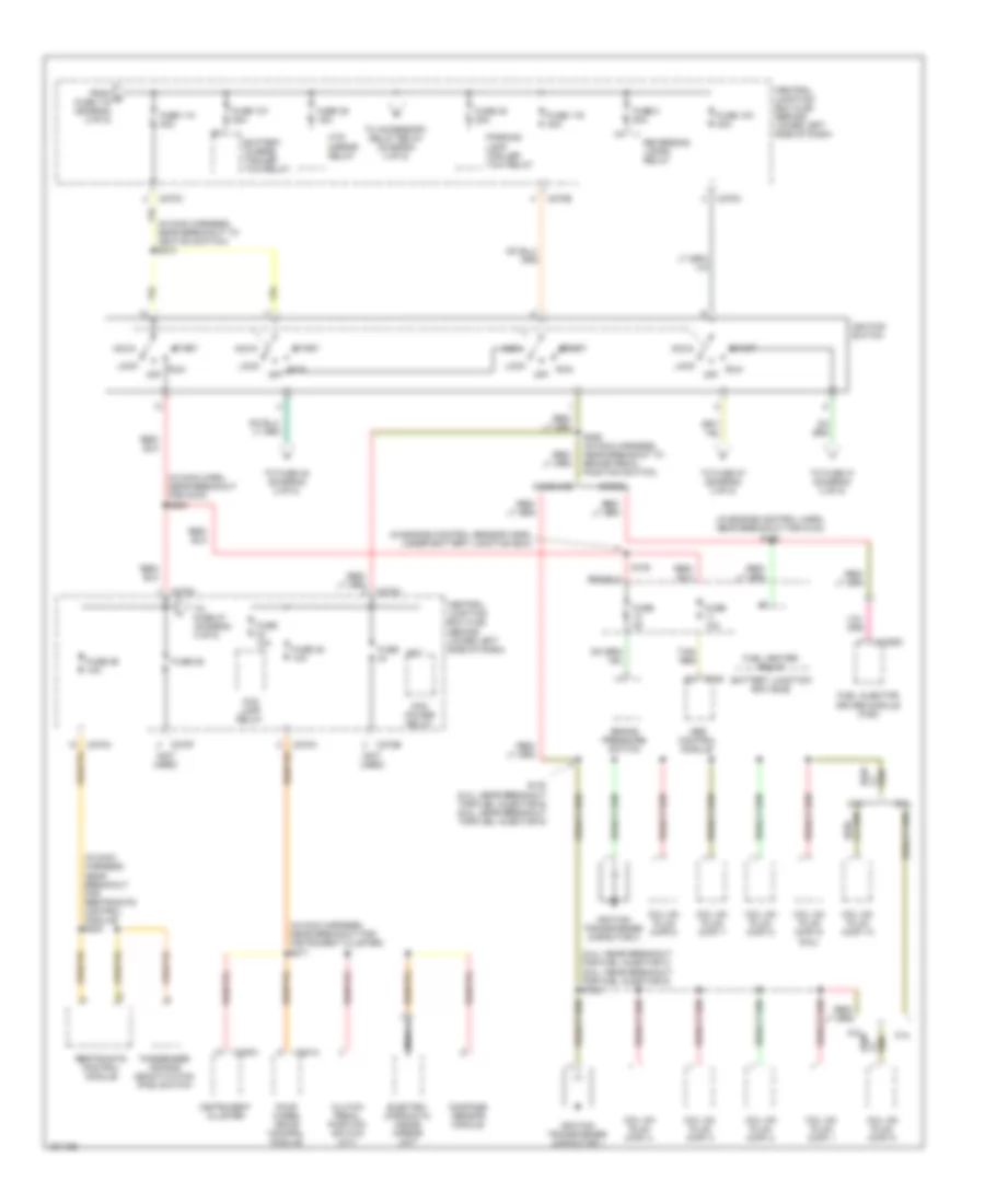
Power Distribution Wiring Diagram (2 of 5) for Ford Cab & Chassis F350 Super Duty 2005
 https://portal-diagnostov.com/license.html
Automotive Electricians Portal FZCO
Automotive Electricians Portal FZCO
https://portal-diagnostov.com/license.html
https://portal-diagnostov.com/license.html
Automotive Electricians Portal FZCO
Automotive Electricians Portal FZCOList of elements for Power Distribution Wiring Diagram (2 of 5) for Ford Cab & Chassis F350 Super Duty 2005:
- (behind lower left side of dash) central junction box (cjb)
- (in alternator harn, near connector) s165
- (in alternator rectifier system harn, near battery positive cable)
- (in body main harn, near breakout for g300) s289
- (in engine control sensor and fuel charge harn, near breakout to c188)
- (in engine control sensor harn, near breakout for c1273a) red s125
- (in main harness, at breakout for instrument cluster) s254
- (not used)
- C102a
- C102c
- C1251a
- C1251c
- C1273a
- C1273b
- C2113b
- C2142a
- C220a
- C270a
- C270b
- C270c
- C270d
- C270e
- C270f
- C270g
- C270h
- C270i
- C270j
- C270k
- C281a
- C290a
- Central junction box (cjb) (behind lower left side of dash)
- Diesel
- Driver side door lock switch
- Driver side front seat adjust switch
- Except diesel
- Four- wheel drive control module
- From battery (diagram 1 of 5)
- From d fuse 112 (diagram 2 of 5)
- From fuse 111 (diagram 1 of 5)
- From ignition switch (diagram 3 of 5)
- Fuel pump relay
- Fuel tank selector switch (w/ auxiliary fuel tank, diesel only)
- Fuse
- Fuse (not used)
- Fuse (not used)
- Fuse 101 30a
- Fuse 102 30a
- Fuse 10a
- Fuse 112 30a
- Fuse 15a
- Fuse 20a
- Fuse 30a
- Fuse 33 15a
- Fuse 5a
- Fusible link e
- Fusible link h
- Generator
- Glow plug control module (gpcm)
- Horn relay
- Instrument cluster
- Nca
- Passenger side door lock switch
- Pcm power relay
- Radio
- Red
- S125 (in engine control sensor harn, near breakout for c1273a)
- S126 (in engine control sensor and fuel charge harn, near breakout to c1273a)
- S143
- S147 (near breakout for positive battery terminal)
- S149
- S149 (in engine control sensor and fuel charge harn, near breakout to c1273a)
- S166 (in alternator harn, near connector)
- Secondary generator (w/ dual generators)
- Starter relay
- To fuse (diagram 3 of 5)
- To fuse 104 (diagram 2 of 5)
- To instrument cluster (diagram 4 of 5)
- Trailer electronic brake control module
- Upfitter relay
- Upfitter relay 1
- Upfitter relay 2
- Upfitter relay 3
- Upfitter relay 4
- Upfitter relay box (right side of dash)
- Vehicle security module (vsm)
- W/ remote keyless entry
- W/o remote keyless entry
- Windshield wiper motor
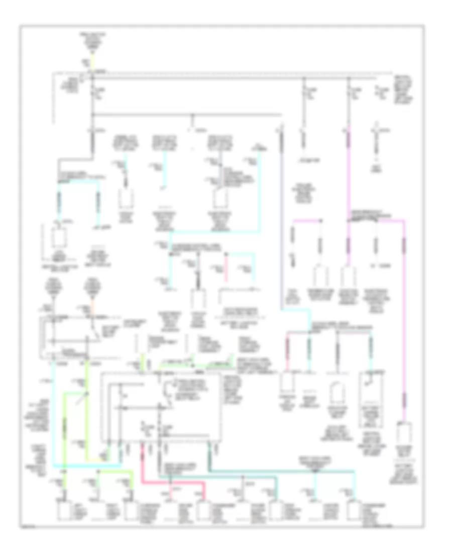
Power Distribution Wiring Diagram (3 of 5) for Ford Cab & Chassis F350 Super Duty 2005
 https://portal-diagnostov.com/license.html
Automotive Electricians Portal FZCO
Automotive Electricians Portal FZCO
https://portal-diagnostov.com/license.html
https://portal-diagnostov.com/license.html
Automotive Electricians Portal FZCO
Automotive Electricians Portal FZCOList of elements for Power Distribution Wiring Diagram (3 of 5) for Ford Cab & Chassis F350 Super Duty 2005:
- (5.4l: near breakout for fuel injector 3) (6.8l: near breakout for fuel injector 5) s135
- (in engine control harn, near breakout for g100) s182
- (in engine control sensor harn, under battery junction box)
- (in main harn, near breakout for c278) s260
- (in main harness, near breakout for instrument cluster) s271
- (in main harness, near breakout for restraints control module) s202
- (in main harness, near breakout to ignition switch) s210
- (not used)
- 5.4l
- 6.8l
- Abs control module
- Acc
- Battery charge trailer tow relay
- Battery junction box (bjb)
- Brake pressure switch
- C135
- C1388c
- C220a
- C270a
- C270b
- C270c
- C270e
- C270f
- C281a
- Central junction box (cjb) (behind lower left side of dash)
- Clutch pedal position switch (m/t)
- Coil on plug (cop) 1
- Coil on plug (cop) 10
- Coil on plug (cop) 2
- Coil on plug (cop) 3
- Coil on plug (cop) 4
- Coil on plug (cop) 5
- Coil on plug (cop) 6
- Coil on plug (cop) 7
- Coil on plug (cop) 8
- Coil on plug (cop) 9 (6.8l)
- Compass sensor module
- Diesel
- Electro- chromatic inside mirror unit
- Fog lamp relay
- Four wheel drive control module
- From e fuse 115 (diagram 2 of 5)
- Fuel heater relay
- Fuel injector driver module (ficm)
- Fuse
- Fuse 103 30a
- Fuse 107 20a
- Fuse 10a
- Fuse 110 30a
- Fuse 116 30a
- Fuse 25
- Fuse 26 10a
- Fuse 2a
- Fuse 38 20a
- Fuse 39 15a
- Fuse 45 10a
- Fuse 8 20a
- Gasoline
- Htd mirror relay
- Ignition switch
- Ignition transformer capacitor 1
- Ignition transformer capacitor 2
- Instrument cluster
- Lock
- Nca
- Off
- Parking lamp trailer tow relay
- Passenger air bag deactivation (pad) switch
- Pcm power relay
- Red/
- Restraints control module
- Reversing lamps relay
- Run
- S108
- S130 (5.4l: near breakout for fuel injector 6) (6.8l: near breakout for fuel injector 9)
- S258 (in main harness, near breakout to brake pedal position switch)
- Start
- Tan/ red
- To accessory delay relay (diagram 4 of 5)
- To fuse 27 (diagram 4 of 5)
- To fuse 31 (diagram 2 of 5)
- To fuse 48 (diagram 2 of 5)
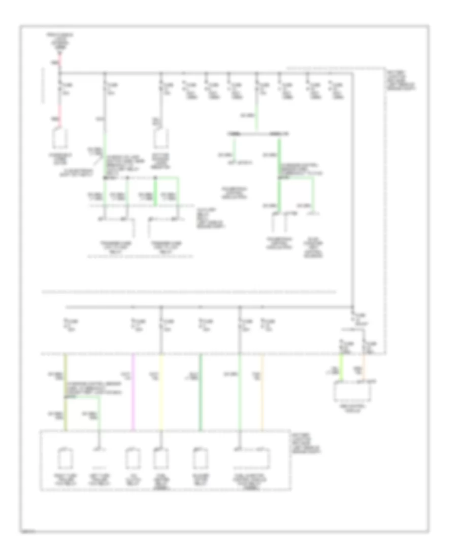
Power Distribution Wiring Diagram (4 of 5) for Ford Cab & Chassis F350 Super Duty 2005
 https://portal-diagnostov.com/license.html
Automotive Electricians Portal FZCO
Automotive Electricians Portal FZCO
https://portal-diagnostov.com/license.html
https://portal-diagnostov.com/license.html
Automotive Electricians Portal FZCO
Automotive Electricians Portal FZCOList of elements for Power Distribution Wiring Diagram (4 of 5) for Ford Cab & Chassis F350 Super Duty 2005:
- (body main harn,
- (body main harn, at breakout for front interior/ map light assembly)
- (body main harn, near breakout for g300)
- (in engine control harn, near breakout for g100) s124
- (in main harn, at breakout to c270j) s209
- (in main harn, near breakout to sunload sensor) s206
- (not used)
- (vanity mirror lamp harn, near breakout to c911) s937
- Accessory delay relay
- All others
- Auxiliary relay box 1 (behind left center of dash)
- Battery charge trailer tow relay
- Battery junction box (bjb)
- Battery junction box (bjb) (left rear of engine compt)
- Battery saver relay
- Blower motor relay
- Brake shift interlock
- C2142b
- C220a
- C220b
- C228b
- C270a
- C270c
- C270d
- C270f
- C270h
- C270i
- C270j
- C359
- C4014
- Central junction box (cjb)
- Central junction box (cjb) (behind lower
- Central junction box (cjb) (behind lower left side of dash)
- Daytime running lamps (drl) relay
- Diesel w/o electronic shift on the fly or drl
- Driver side door lock switch
- Driver side front heated seat module
- Electronic automatic temperature control (eatc) module
- Electronic shift on the fly (ecof) solenoid
- Engine compartment lamp
- From central junction box (diagram 3 of 5)
- From fuse 25 (diagram 3 of 5)
- From fuse 35 (diagram 2 of 5)
- From ignition switch (diagram 3 of 5)
- From j fuse 25 (diagram 3 of 5)
- Front interior/ map lamps assembly
- Function selector switch assembly
- Fuse 10a
- Fuse 15a
- Fuse 30a
- Gas w/ a/t & electronic shift on the fly w/o drl
- Gas w/ m/t & electronic shift on the fly w/o drl
- Htd mirror relay
- Indicator flasher relay
- Instrument cluster
- Left side of dash)
- Left vanity mirror lamp
- Master window adjust switch
- Micro- processor
- Nca
- Near breakout for g300)
- Near breakout to sunload sensor) (in main harn, s235
- Overhead console (w/ roof opening panel)
- Parking aid module (pam)
- Passenger side door lock switch
- Passenger side window adjust switch (w/o crew cab)
- Pnk
- Power sliding rear window switch
- Rear interior/ map lamps assembly
- Right vanity mirror lamp
- Roof opening panel module
- S124 (in engine control harn, near breakout for g100)
- S141
- S219
- S229 (w/ vanity lamps) (main harn, near break- out for instrument cluster)
- S297
- S906
- Temperature blend door actuator
- Tow/ haul switch (w/ a/t)
- Trailer electronic brake control module
- Vacuum pump motor
- Vacuum pump motor (diesel)
Power Distribution Wiring Diagram (5 of 5) for Ford Cab & Chassis F350 Super Duty 2005
 https://portal-diagnostov.com/license.html
Automotive Electricians Portal FZCO
Automotive Electricians Portal FZCO
https://portal-diagnostov.com/license.html
https://portal-diagnostov.com/license.html
Automotive Electricians Portal FZCO
Automotive Electricians Portal FZCOList of elements for Power Distribution Wiring Diagram (5 of 5) for Ford Cab & Chassis F350 Super Duty 2005:
- (diesel)
- (in back up lamp switch harn, near breakout to auxiliary relay box 3) s163
- (in engine control sensor harn, at breakout for battery junction box) s103
- (in engine control sensor harn, in breakout to c140) s164
- A/c clutch relay
- Abs control module
- Auxiliary relay box 3 (left side of engine compt)
- Battery junction box (bjb) (left rear of engine compt)
- Blower motor relay
- C135
- C1381a
- C175b
- Daytime running lamps resistor
- Diesel
- Evap canister vent control solenoid
- From fusible link b (diagram 1 of 5)
- Fuel heater relay (diesel)
- Fuel injector control module (ficm) relay
- Fuse (not used)
- Fuse 10a
- Fuse 15a
- Fuse 20a
- Fuse 30a
- Fuse 40a
- Fuse 50a
- Fuse 60a
- Fuse shunt
- Gasoline
- Left turn trailer tow relay
- Nca
- Powertrain control module (pcm)
- Red
- Right turn trailer tow relay
- Transfer case high to low relay
- Transfer case low to high relay
- W/ electronic shift on the fly
- Windshield wiper motor

 Čeština
 Dansk
Dansk Deutsch
 Ελληνικά
 English
 English
 Español
 Suomi
Suomi Français
 Français
 Hrvatski
 Magyar
 Italiano
 日本語
日本語 한국어
한국어 Nederlands
 Polski
 Português
 Português
 Română
 Русский
 Slovenčina
 Slovenščina
 Svenska
 Türkçe
 中文 (中国)
