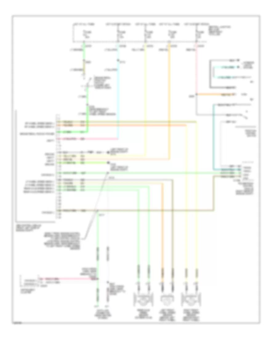
ANTI-LOCK BRAKES
Anti-lock Brakes Wiring Diagram for Ford Pickup F150 2006
List of elements for Anti-lock Brakes Wiring Diagram for Ford Pickup F150 2006:
- (early prod: engine control sensor harn, near breakout to abs control module, late prod: engine control sensor harn, near breakout to left front wheel speed sensor)
- (left front of engine compt) g110
- (main wiring harn, near breakout to c2026) s288
- Abs control module (front left side of engine compt)
- Brake pedal pos sw power
- Brake pedal position switch (under left side of dash)
- C175b
- C220a
- C270b
- C270c
- C270d
- C270f
- Can bus (+)
- Can bus (-)
- Can+
- Can-
- Central junction box (cjb) (near right "a" pillar)
- Data link connector (near center of dash)
- Fuse 10a
- Fuse 20a
- Fuse 40a
- Fuse 5a
- G108 (left front of engine compt)
- Ground
- Hot at all times
- Hot in start or run
- Instrument cluster
- Interior lights system
- Left front wheel speed sensor (behind left front wheel)
- Lf wheel speed sens (+)
- Lf wheel speed sens (-)
- Nca
- Powertrain control module (right rear of engine compt)
- Rear axle speed sens (+)
- Rear axle speed sens (-)
- Rear axle speed sensor (on rear axle)
- Rf wheel speed sens (+)
- Rf wheel speed sens (-)
- Right front wheel speed sensor (behind right front wheel)
- S109 (near breakout to left front wheel speed sensor)
- S112
- S116
- S117
- S118
- S220
- S225
- S287 (main wiring harn, near breakout to c2026)
- Tracil
- Tracs
- Traction control switch
- Vbatt
 Čeština
 Dansk
Dansk Deutsch
 Ελληνικά
 English
 English
 Español
 Suomi
Suomi Français
 Français
 עברית
עברית Hrvatski
 Italiano
 日本語
日本語 한국어
한국어 Nederlands
 Polski
 Português
 Português
 Română
 Русский
 Slovenčina
 Slovenščina
 Svenska
 Türkçe
 中文 (中国)
 Magyar