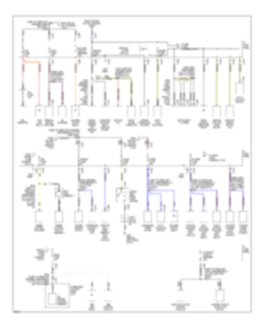
POWER DISTRIBUTION
Power Distribution Wiring Diagram (1 of 2) for Mercury Tracer GS 1997
 https://portal-diagnostov.com/license.html
Automotive Electricians Portal FZCO
Automotive Electricians Portal FZCO
https://portal-diagnostov.com/license.html
https://portal-diagnostov.com/license.html
Automotive Electricians Portal FZCO
Automotive Electricians Portal FZCO
List of elements for Power Distribution Wiring Diagram (1 of 2) for Mercury Tracer GS 1997:
- (dash to headlamp harness, near breakout to c202, front of center console) s218
- (dash to headlamp harness, near breakout to one touch control unit) s222
- (dash to headlamp harness, near grommet) s127
- (engine harness, in breakout to engine compt fuse box) s102
- (engine harness, near breakout to engine compt fuse box) s104
- (main harness, near breakout to i/p fuse panel) s217
- (not used)
- (rear harness, near breakout to left rear courtesy lamp switch) s300
- Abs main relay
- Abs maxi fuse 60a
- Acc
- Air bag diagnostic monitor
- Battery
- Brake on/off (boo) switch
- Brake pressure switch
- Btn maxi fuse 40a
- C108
- C109
- C110
- C133
- C147
- C156
- C157
- C159
- C160
- C210
- C232
- C240
- C250
- C252
- C260
- C263
- C270
- C274
- C281
- C283
- C295
- C404
- Constant control relay module (ccrm)
- Cooling fan maxi fuse 40a
- Data link conn- ector (dlc)
- Defog maxi fuse 30a
- Dome/ map lamp assembly
- Door lock fuse 30a
- Door lock/ unlock relay
- Electronic flasher
- Engine compart- ment fuse box
- Engine compartment fuse box
- From a btn fuse (diagram 1 of 2)
- Fuel injector maxi fuse 30a
- Fuel pump fuse 30a
- Generator
- Hazard fuse 15a
- Head- lamp relay
- Horn fuse 15a
- Horn relay
- I/p fuse panel
- Ignition switch
- Inhibit relay
- Instrument cluster
- Integrated control panel (icp)
- Key in ignition switch
- Left head fuse 20a
- Lock
- Luggage compart- ment lamp
- Main maxi fuse 100a
- Multi-function switch
- Nca
- Obd ii fuse 10a
- Park lamp relay
- Power- train control module (pcm)
- Rear window defogger relay
- Red
- Remote anti-theft personality (rap) module
- Right head fuse 20a
- Room fuse 10a
- Run
- S103 (charge harness, near breakout to engine compt fuse box)
- S105 (charge harness, near breakout to battery)
- S209 (dash to headlamp harness, near breakout to c233, upper left kick panel)
- S210 (dash to headlamp harness, near breakout to multi-function switch)
- S216 (dash to head- lamp harn, near break- out to one touch down control unit)
- S306 (rear harn, near break- out to left rear crtsy lp sw)
- Sedan
- Shift lock actuator
- Start
- Starter assembly
- Stop fuse 15a
- Tail fuse 15a
- To abs fuse (diagram 1 of 2)
- To i/p fuse panel, engine fuse (diagram 2 of 2)
- To i/p fuse panel, wiper fuse (diagram 2 of 2)
- To splice s126 (diagram 2 of 2)
- To splice s211 (diagram 2 of 2)
- Wagon
- Wagon only
- Warning chime module
Power Distribution Wiring Diagram (2 of 2) for Mercury Tracer GS 1997
List of elements for Power Distribution Wiring Diagram (2 of 2) for Mercury Tracer GS 1997:
- (dash to headlamp harn, near breakout to c225, left kick panel) s221
- (dash to headlamp harn, near breakout to joint connector #4, left side of i/p) s219
- (dash to headlamp harn, near breakout to multi-function switch) s213
- (dash to headlamp harness, near breakout to i/p fuse panel) s211
- (fuel injector harness, near breakout to ignition coil) s107
- (main harn, near break- out to instru- ment cluster) s214
- (main harness, near breakout to i/p fuse panel) s223
- (not used)
- (rear harn, near break- out to c400, right rear trunk area) s409
- (rear harn, near break- out to i/p fuse panel) s215
- A/c- heater control assembly
- Abs control module
- Abs main relay
- Air bag diagnostic monitor
- Asc fuse 10a
- Backup/ upshift switch (m/t)
- Blower circuit breaker 30a
- Blower motor relay
- C147
- C200
- C210
- C220
- C226
- C227
- C231
- C239
- C240
- C246
- C251
- C252
- C253
- C254
- C260
- C270
- C274
- C277
- C305
- C386
- C405
- Cd changer
- Cigar fuse 20a
- Constant control relay module (ccrm)
- Daytime running lamps (drl) module
- Drl fuse 10a
- Drl resistor
- Engine coolant level switch
- Engine fuse 15a
- Fog fuse 10a
- Fog lamp relay
- From d ignition switch (diagram 1 of 2)
- From e ignition switch (diagram 1 of 2)
- From f meter fuse (diagram 2 of 2)
- From ignition switch (diagram 1 of 2)
- From r g wiper fuse (diagram 2 of 2)
- From splice s127 (diagram 1 of 2)
- G201 (behind right side of i/p)
- Hego fuse 10a
- I/p fuse panel
- Ignition coil
- Instru- ment panel cigar lighter
- Instrument cluster
- Integrated control panel (icp)
- Joint conn- ector #7
- Left daytime running lamp (drl) relay
- Liftgate washer pump motor (wagon)
- Liftgate wiper motor (wagon)
- Master window/ door lock switch
- Meter fuse 15a
- Mirror fuse 5a
- Multi- function switch
- Nca
- One touch down control module
- P window circuit breaker 30a
- Power mirror switch
- Premium sound amplifier
- R wiper fuse 10a
- Radio fuse 15a
- Radio noise capacitor
- Rear window defogger relay
- Red bkl/
- Remote anti- theft person- ality (rap) module
- Right daytime running lamp (drl) relay
- S106 (engine harness, near break- out to egr vacuum reg- ulator)
- S220 (main harn, near break- out to instru- ment clus- ter)
- S232 (dash to headlamp harness, near break- out to joint connector #4, left side of i/p)
- S234 (dash to headlamp harness, near break- out to c219, upper left kick panel)
- Shift lock actuator
- Slip ring assembly
- Speed control amplifier
- Speed control switch assembly
- To asc fuse (diagram 2 of 2)
- To hego fuse (diagram 2 of 2)
- Trans- mission range (tr) sensor (a/t)
- Warning chime module
- Windshield wiper motor
- Wiper fuse 20a

 Čeština
 Dansk
Dansk Deutsch
 Ελληνικά
 English
 English
 Español
 Suomi
Suomi Français
 Français
 עברית
עברית Hrvatski
 Italiano
 日本語
日本語 한국어
한국어 Nederlands
 Polski
 Português
 Português
 Română
 Русский
 Slovenčina
 Slovenščina
 Svenska
 Türkçe
 中文 (中国)