POWER DISTRIBUTION
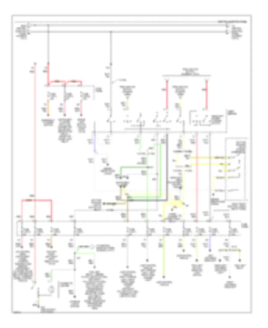
Power Distribution Wiring Diagram (1 of 4) for Audi A8 1997
 https://portal-diagnostov.com/license.html
Automotive Electricians Portal FZCO
Automotive Electricians Portal FZCO
https://portal-diagnostov.com/license.html
https://portal-diagnostov.com/license.html
Automotive Electricians Portal FZCO
Automotive Electricians Portal FZCO
List of elements for Power Distribution Wiring Diagram (1 of 4) for Audi A8 1997:
- 1998,
- 50b
- 86s
- A22
- Abs control module
- Abs control module (1998-99 quattro)
- Abs hydraulic unit
- Amplifier, left/right rear woofer, power antenna, radio
- Battery
- Central electric panel
- Central locking/ alarm system/ interior light delay control module
- Connector tv1
- Connector tv2
- D50/a32
- Daytime running lights switch on relay
- Dual horn relay
- Dual horns
- E20/a32
- Evaporative emission canister purge regulator valve, intake change-over valve, fuel injector air control valve, leak detection pump
- Fuse 15a
- Fuse 20a
- Fuse 25a
- Fuse 50a
- Fuse 8 (st1) 15a
- Fuse 9 (st4) 5a
- Fuse panel
- G43 (above right kick panel)
- Ignition switch
- Instrument cluster, central locking/ alarm system/ interior light delay control module, radio, steering column/belt height control module
- Key-in ignition switch
- Left/right rear head rest adjustment switch, left/right rear head rest lower relay, left/right rear seat lumbar support height adjustment switch
- Left/right rear seat regulating switch
- Load reduction relay
- Motronic engine control module
- Motronic engine control module, fuel injectors
- Off
- Plenum chamber e-box relay & fuse panel
- Red
- Relay & fuse panel
- Run
- S1/
- S1/ 30ah
- S1/ 87h
- S1/50z
- S4/50z
- S4/a
- S4/b
- S6/50a
- Start
- Starter
- Starting interlock relay
- Steering wheel control module
- Telephone transceiver
- To central electric panel (diagram 2 of 4)
- To fuse 6 (st3) (diagram 3 of 4)
- To light switch (diagram 2 of 4)
- Transmission control module
- Voltage regulator/ generator
- Voltage regulator/ generator, instrument cluster
- Wiper/washer intermittent relay
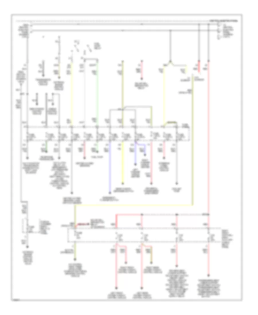
Power Distribution Wiring Diagram (2 of 4) for Audi A8 1997
List of elements for Power Distribution Wiring Diagram (2 of 4) for Audi A8 1997:
- (diagram 1 of 4)
- 75x
- A/c control head, instrument panel interior temperature sensor, instrument cluster, solar cell separation relay, steering wheel control module
- A37
- A51
- Brake light switch, vacuum dump valve
- Central electric panel
- Cigarette lighter
- Coolant pump, left/right heat regulating valve
- Daytime running lights change- over relay
- Daytime running lights switch on relay
- E107
- E108
- E109
- E116
- Emergency flasher switch
- Fog light relay
- Fog light relay, license plate lights (w/o drl), left/right taillights (w/o drl), ashtray light, multi-function transmission range switch, selector lever light relay protection diode, telephone transceiver, a/c control head
- Fog light switch, rear fog light switch
- From a central electric panel b
- From ignition switch (diagram 1 of 4)
- Fuse 1 (st1) 5a
- Fuse 2 (st1) 5a
- Fuse 3 (st1) 15a
- Fuse 3 (st2) 5a
- Fuse 3 (st3) 15a
- Fuse 4 (st1) 15a
- Fuse 4 (st3) 5a
- Fuse 5 (st1) 10a
- Fuse 5 (st2) 15a
- Fuse 6 (st1) 10a
- Fuse 7 (st1) 15a
- Fuse 7 (st3) 15a
- Fuse 9 (st1) 5a
- Fuse 9 (st2) 10a
- Fuse panel
- G43 (above right kick panel)
- Headlight beam adjustment control module
- Headlight dimmer/ flasher switch
- Headlight high beam indicator light
- Instrument cluster
- Instrument cluster, data link connector, solar cell separation relay, selector lever light relay
- Interior lights system
- Lamp control module
- Lamp control module, right parking light, right front side marker light left/right taillights (w/ drl), license plate lights (w/ drl)
- Lamp control module, left parking light, left front side marker light
- Left high beam headlight
- Light light switch switch
- Red
- Right front footwell e-box relay panel
- Right high beam headlight
- Series resistance wiring
- To central electric panel (diagram 3 of 4)
- To central electric panel (diagram 4 of 4)
- W/ drl
- W/o drl
- W/o drl w/ drl
- Wiper/ washer intermittent relay
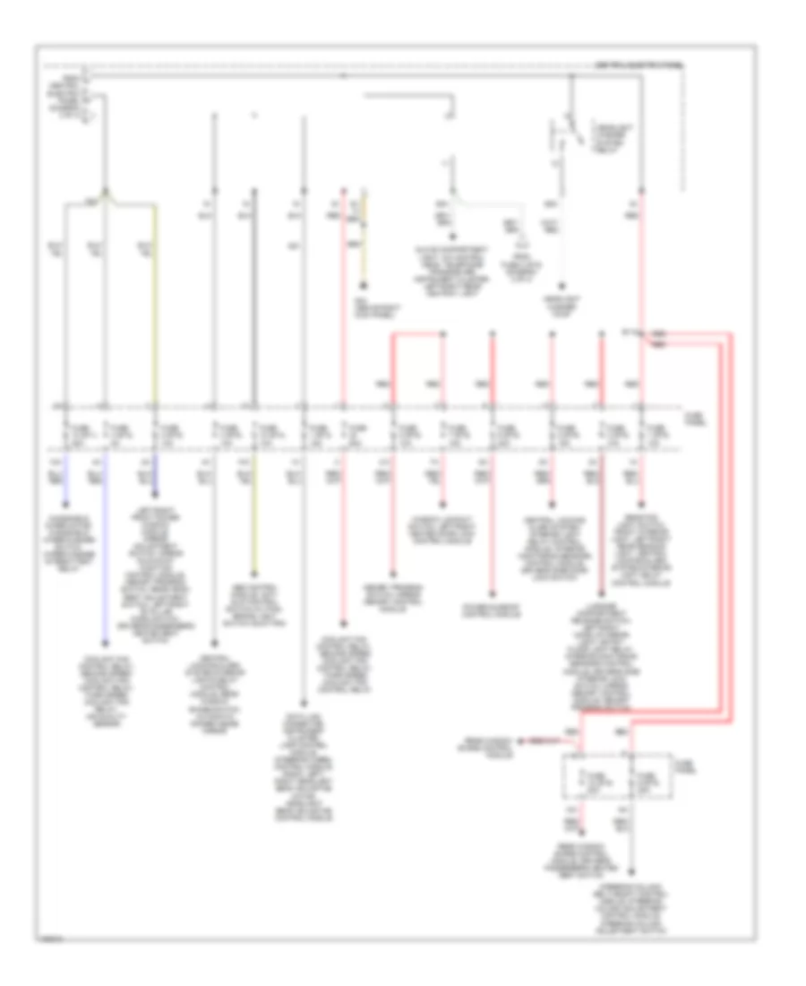
Power Distribution Wiring Diagram (3 of 4) for Audi A8 1997
List of elements for Power Distribution Wiring Diagram (3 of 4) for Audi A8 1997:
- 10a
- 75x
- 87f/ dti
- A/c clutch relay, a/c refrigerant low pressure switch, left/right heat regulating valves, thermotronic control module, a/c control head
- A/c control head, fresh air blower, interior monitoring sensors control module
- A34
- Airbag control module
- B110
- C.b. 30a
- Central electric panel
- Central electric panel (diagram 2 of 4)
- Coolant pump
- Driver's & passenger's side mirror
- Emergency flasher switch
- From g
- From ignition switch (diagram 1 of 4)
- Fuel pump
- Fuel pump relay
- Fuse 1 (st2) 10a
- Fuse 1 (st4) 15a
- Fuse 10 (st2) 5a
- Fuse 2 (st3) 10a
- Fuse 20a
- Fuse 3 (st4) 20a
- Fuse 4 (st4) 15a
- Fuse 40a
- Fuse 5 (st3) 15a
- Fuse 6 (st2) 30a
- Fuse 6 (st3) 10a
- Fuse 8 (st2) 10a
- Fuse 8 (st3) 15a
- Fuse 9 (st3) 10a
- Fuse panel
- Heated oxygen sensors
- Heated oxygen sensors, mass air flow sensor
- Left front power window control module
- Left rear power window control module
- Left washer nozzle heater
- Motronic engine control module
- Motronic engine control module, ignition coils
- Multi-function transmission range switch, shift lock solenoid
- Passenger's seat lumbar support adjustment switch, passenger's seat adjustment switch, passenger's belt height adjustment
- Plenum chamber e-box relay & fuse panel
- Rear window defogger switch
- Red
- Right front footwell e-box auxiliary fuse & relay panel
- Right front power window control module
- Right rear power window control module
- Right washer nozzle heater
- S2/87f
- S3/
- S3/ 87a
- S3/s
- Servotronic control module
- Solar cell separation relay
- Solar cell separation relay (w/ sunroof)
- Steering wheel control module
- Switch
- Telephone transceiver
- To central electric panel (diagram 4 of 4)
- Transmission control module
- W/ sunroof
- W/o sunroof
Power Distribution Wiring Diagram (4 of 4) for Audi A8 1997
List of elements for Power Distribution Wiring Diagram (4 of 4) for Audi A8 1997:
- (diagram 3 of 4)
- 10a
- 58a
- 75x
- Abs control module, anti- slip control switch (w/ fwd), brake light switch (quattro)
- B115
- Central electric panel
- Central locking/ alarm system/ interior light delay control module, interior monitoring sensors control module, driver's side door lock switch
- Central locking/alarm system/interior lights delay control module, rear window shade switch, automatic dimmer inside mirror
- Coolant fan control relay, second speed coolant fan control relay, third speed coolant fan control relay
- Coolant fan control relay, second speed coolant fan control relay, third speed coolant fan relay, air quality sensor
- D51
- Data link connector, instrument cluster, lamp control module, steering wheel control module, radio, left/ right headlight beam adjusting motor, headlight beam adjusting control module
- From fuse 3 (st2) (diagram 2 of 4)
- From j central electric panel k
- Fuse 1 (st3) 15a
- Fuse 1 (st5) 10a
- Fuse 10 (st1) 25a
- Fuse 10 (st4) 10a
- Fuse 10 (st5) 20a
- Fuse 2 (st5) 10a
- Fuse 3 (st5) 10a
- Fuse 4 (st2) 5a
- Fuse 4 (st5) 10a
- Fuse 5 (st5) 15a
- Fuse 6 (st5) 20a
- Fuse 60a
- Fuse 7 (st5) 15a
- Fuse 8 (st5) 10a
- Fuse 9 (st5) 20a
- Fuse panel
- G43 (above right kick panel)
- Glove compartment light, a/c control head, telephone transceiver, instrument cluster, left/right rear ashtray light
- Headlight washer pump
- Headlight washer system relay
- Left/right front power window module, mirror adjustment switch, mirror fold-away function control module, memory program switch, rear head- rest adjustment switch, left/right "b" pillar micro switch, driver's/passenger's heated seat switch
- Luggage compartment release switch, left/right make up mirror light, entry/ floor light relay, interior monitoring sensors control module, driver's side interior lock switch, mirror memory control module, memory program switch
- Memory program switch, mirror memory control module
- Power sunroof control module
- Rear fog light switch, front interior light, left/right rear reading light, central locking/alarm system/interior light delay control module
- Rear window shade control module
- Rear window shade control module, driver's/ passenger's heated seat switch
- Red
- S1/
- S5a
- Steering column/ belt height control module, steering column adjustment control module, steering column adjustment switch
- Window lockout switch, left/right heated door lock control module
- Windshield wiper motor, windshield wiper/washer switch, wiper/washer intermittent relay

 Čeština
 Dansk
Dansk Deutsch
 Ελληνικά
 English
 English
 Español
 Suomi
Suomi Français
 Français
 עברית
עברית Hrvatski
 Magyar
 日本語
日本語 한국어
한국어 Nederlands
 Polski
 Português
 Português
 Română
 Русский
 Slovenčina
 Slovenščina
 Svenska
 Türkçe
 中文 (中国)