ANTI-THEFT
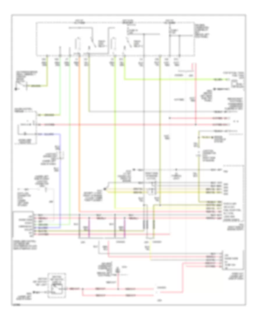
Forced Entry Wiring Diagram for Honda Odyssey Touring 2010
 https://portal-diagnostov.com/license.html
Automotive Electricians Portal FZCO
Automotive Electricians Portal FZCO
https://portal-diagnostov.com/license.html
https://portal-diagnostov.com/license.html
Automotive Electricians Portal FZCO
Automotive Electricians Portal FZCO
List of elements for Forced Entry Wiring Diagram for Honda Odyssey Touring 2010:
- (behind right rear side trim panel) micu-rear junction box
- (on right "c" pillar) right sliding door switch
- A14
- A25
- B-can drswdr
- Body controller area network transceiver
- Driver's door switch (on left "b" pillar)
- Driver's under-dash fuse/relay box (behind left kick panel)
- Drswas
- Drswra
- Drswrd
- E14
- E15
- Front passenger's door switch (on right "b" pillar)
- Fuse 33 2a
- G60
- G701 (behind right rear side trim panel)
- Gauge control module
- H12
- H13
- Hot at all times
- Left sliding door switch (on left "c" pillar)
- Micro- phone jack
- Microphone
- Micu
- Micu-rear junction box control unit
- N28
- Nca
- Security control unit
- Tailgate latch switch
Immobilizer Wiring Diagram for Honda Odyssey Touring 2010
List of elements for Immobilizer Wiring Diagram for Honda Odyssey Touring 2010:
- (behind right kick panel)
- (on parking brake pedal assembly) parking brake switch
- (right side of engine)
- (top of fuel tank) fuel tank unit
- (under left side of dash)
- (under left side of dash) junction connector c503
- 1=key in ignition
- A11
- A16
- A41
- A46
- B40
- B41
- B42
- C41
- Canada
- D12
- Data link connector (dlc) (under left side of dash)
- Diag-h
- Driver's under-dash fuse/relay box (behind left kick panel)
- Driver's underdash fuse/relay box (behind left kick panel)
- E13
- E14
- Engine controls system
- Fuel pump
- Fuel pump ctrl
- Fuse 19 15a
- Fuse 7 7.5a
- G101 (except lx & ex: front of engine) (lx & ex: under throttle body)
- G102 (lx, ex; canada: dx) (front of engine)
- G502
- G603 (behind left rear side trim panel)
- Gauge control module
- Gnd
- H/brake sw
- Hot at all times
- Hot in on or start
- Ig key sw
- Ig1
- Ign in (ig1)
- Ignition
- Ignition key switch
- Immobi code
- Immobi code in
- Immobilizer control unit-receiver (on steering column, near steering lock)
- Immobilizer indicator
- Imoes unit (under left side of dash)
- Imolmp
- J/c c102
- Junction connector c101 (right side of engine)
- Junction connector c503 (under left
- Key light
- Key switch/
- Lg3
- Logic gnd
- Micu
- N30
- N34
- Passenger's under-dash fuse/relay box
- Pcm (right side of engine compt)
- Pg2
- Pgm-fi main relay 1
- Pgm-fi main relay 2
- Pwr in (igp)
- Rly ctrl
- S1 (thermal joint)
- Side of dash)
- Usa
- X31
- X35
- X38

 Čeština
 Dansk
Dansk Deutsch
 Ελληνικά
 English
 English
 Español
 Suomi
Suomi Français
 Français
 עברית
עברית Hrvatski
 Magyar
 日本語
日本語 한국어
한국어 Nederlands
 Polski
 Português
 Português
 Română
 Русский
 Slovenčina
 Slovenščina
 Svenska
 Türkçe
 中文 (中国)