ENGINE PERFORMANCE
5.4L
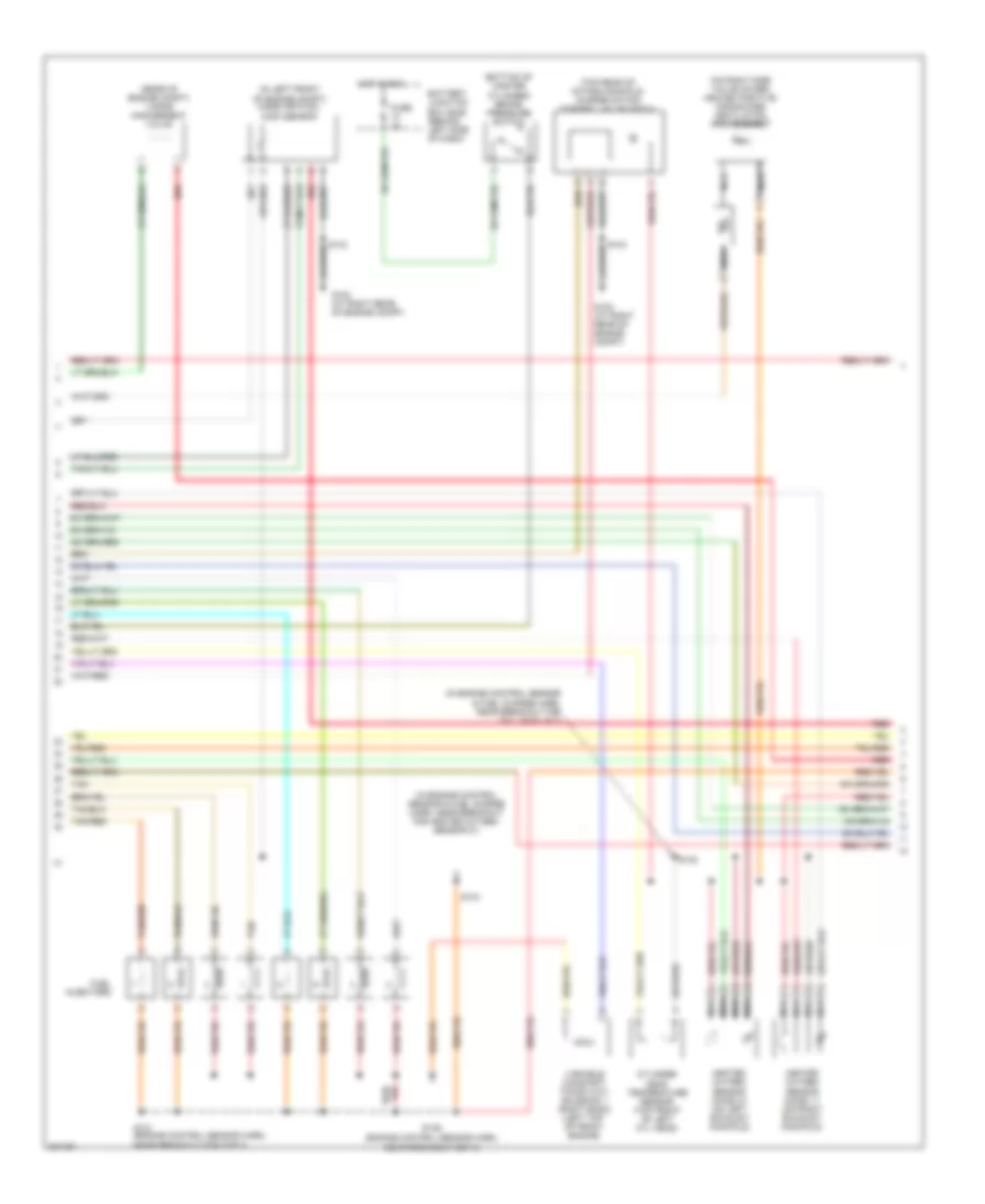
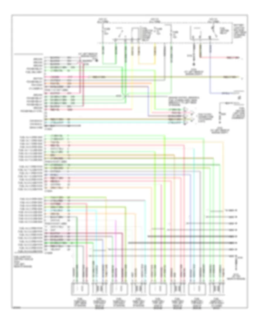
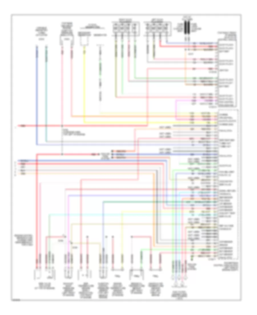
5.4L, Engine Performance Wiring Diagram (1 of 5) for Ford Cab & Chassis F350 Super Duty 2005
 https://portal-diagnostov.com/license.html
Automotive Electricians Portal FZCO
Automotive Electricians Portal FZCO
https://portal-diagnostov.com/license.html
https://portal-diagnostov.com/license.html
Automotive Electricians Portal FZCO
Automotive Electricians Portal FZCO
List of elements for 5.4L, Engine Performance Wiring Diagram (1 of 5) for Ford Cab & Chassis F350 Super Duty 2005:
- (in engine control sensor & fuel charge harn, near breakout for c175a)
- A/c clutch rly
- A/c press sw
- A/c system
- Brake pressure sw
- C175a
- Camshaft position sensor (left bank) (on lower front center of engine)
- Camshaft position sensor (right bank) (on lower right front of engine)
- Ckp sensor +
- Ckp sensor -
- Cmcv cntrl
- Cmcv monitor
- Cmp sensor 1
- Cmp sensor 2
- Coil on plug
- Coil on plug 1
- Coil on plug 2
- Coil on plug 3
- Coil on plug 4
- Coil on plug 5
- Coil on plug 6
- Coil on plug 7
- Coil on plug 8
- Crankshaft position sensor (on front of left cylinder head)
- Cyl head temp
- Engine oil temperature sensor (eot) (lower right rear of engine block)
- Eot sensor
- Etc motor
- Fuel inj 1
- Fuel inj 2
- Fuel inj 3
- Fuel inj 4
- Fuel inj 5
- Fuel inj 6
- Fuel inj 7
- Fuel inj 8
- Fuel rail press sen
- Fuel rail temp sens
- Ho2s 11 htr
- Ho2s 11 input
- Ho2s 21 htr
- Ho2s 21 input
- Iat sensor
- Ignition transformer capacitor 1 (right front of engine)
- Ignition transformer capacitor 2 (on rear of right cylinder head)
- Injection pressure sensor (ips) (top left center of intake manifold)
- Knock sensor 1 +
- Knock sensor 1 -
- Knock sensor 2 +
- Knock sensor 2 -
- Maf sensor
- Nca
- Pcv valve
- Powertrain control module (on left side of firewall)
- Reference voltage
- S130 (in engine control sensor & fuel charge harn, near breakout for fuel inj 6)
- S135 (in engine control sensor & fuel charge harn, near breakout for fuel inj 3)
- S145
- Shield drain
- Signal return
- Tan
- Tan/red
- Throttle position sensor (top of engine, near air intake)
- Tps 1 sig
- Tps 2 sig
- Tps ref
- Tps sig return
- Vapor man valve
- Vct sol 1
- Vct sol 2
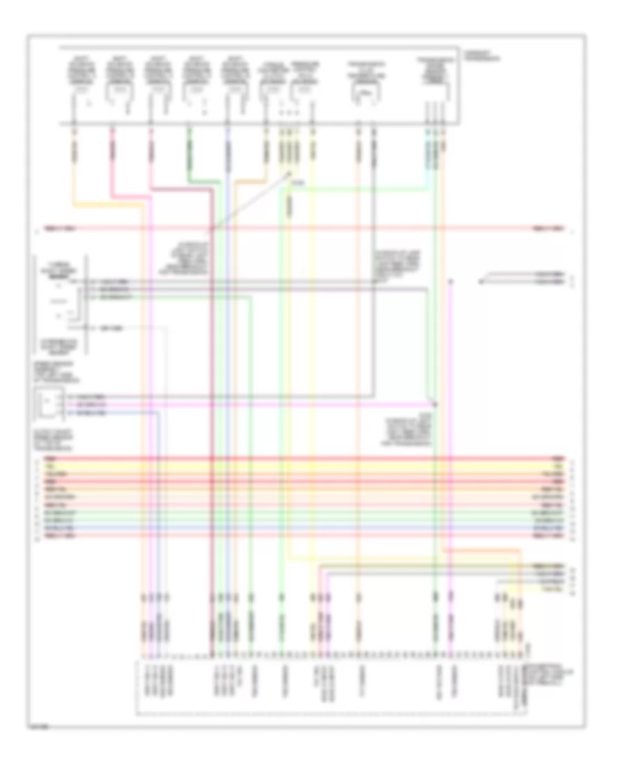
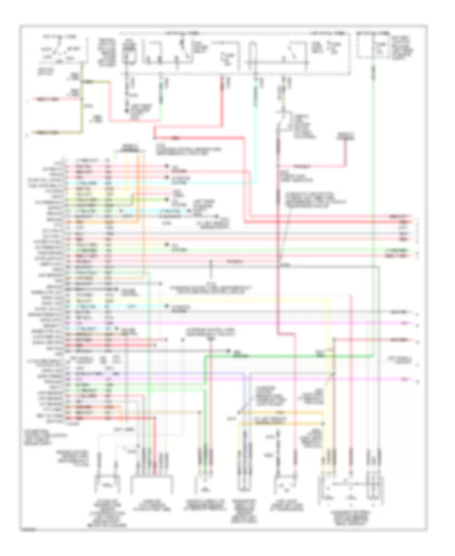
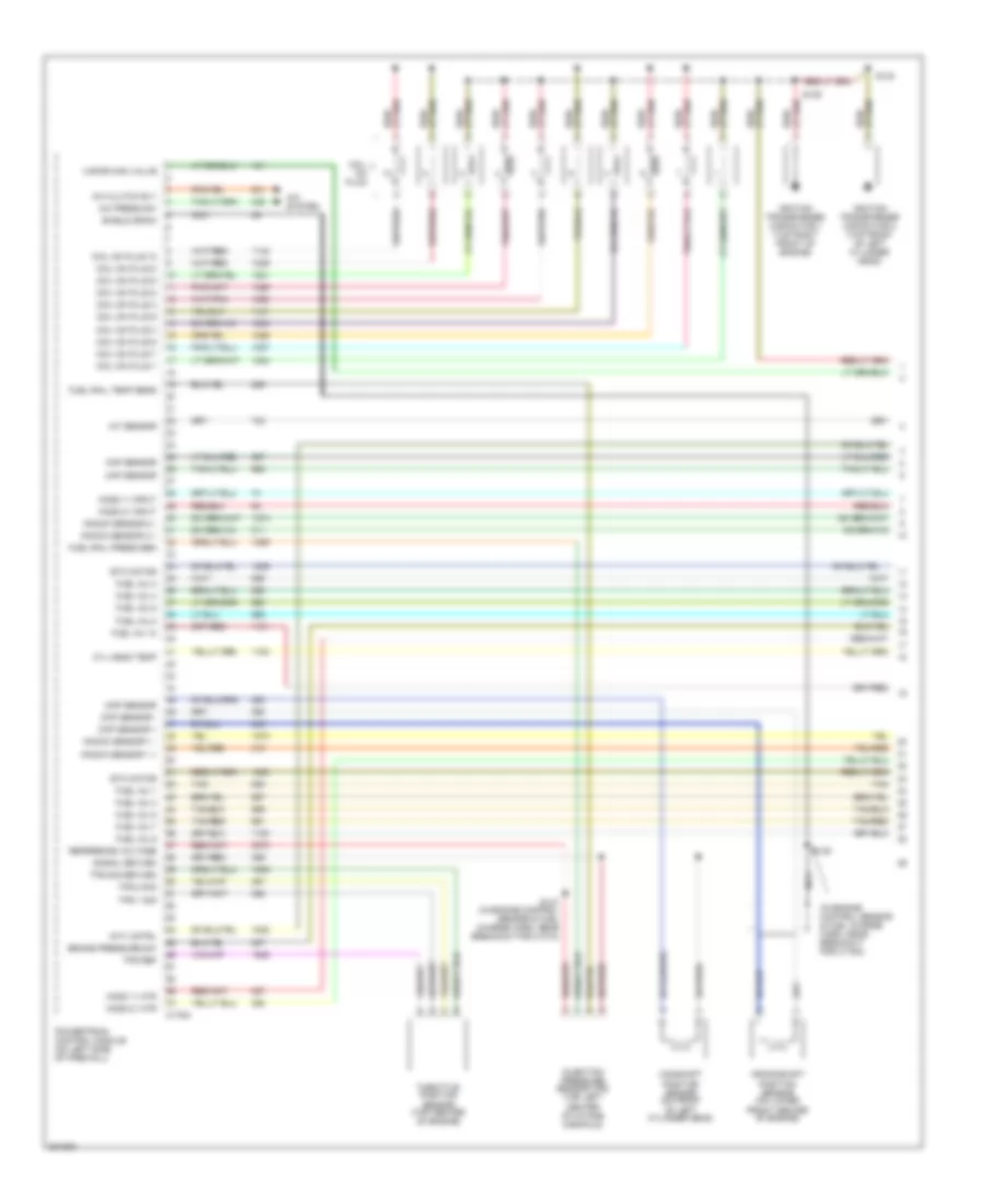
5.4L, Engine Performance Wiring Diagram (2 of 5) for Ford Cab & Chassis F350 Super Duty 2005
List of elements for 5.4L, Engine Performance Wiring Diagram (2 of 5) for Ford Cab & Chassis F350 Super Duty 2005:
- (bottom of master cylinder) brake pressure switch
- (engine control sensor harn, near breakout cop 3)
- (engine control sensor harn, near breakout for cop 7)
- (in engine control sensor & fuel charge harn, near breakout for coil on plug 7)
- (in engine control sensor & fuel charge harn, near breakout for heated oxygen sensor 21)
- (in left front of engine compt) mass air flow (maf) sensor
- (on right side valve cover) heated positive crankcase ventilation (pcv) element
- (rear of engine compt) vapor management valve
- (top rear of intake manifold) charge motion control valve (cmcv)
- Battery junction box (bjb) (behind left side of dash)
- Cylinder head temperature sensor (top front of left cyl head)
- Fuel injectors
- Fuse 2a
- G102 (at right rear of engine compt)
- Heated oxygen sensor (ho2s) 11 (on right exhaust manifold)
- Heated oxygen sensor (ho2s) 21 (on left exhaust manifold)
- Hot in run
- Nca
- Red
- S131
- S132
- S134
- S136
- Tan
- Tan/red
- Variable camshaft timing (vct) solenoid 1 (right bank) (left top of front engine)
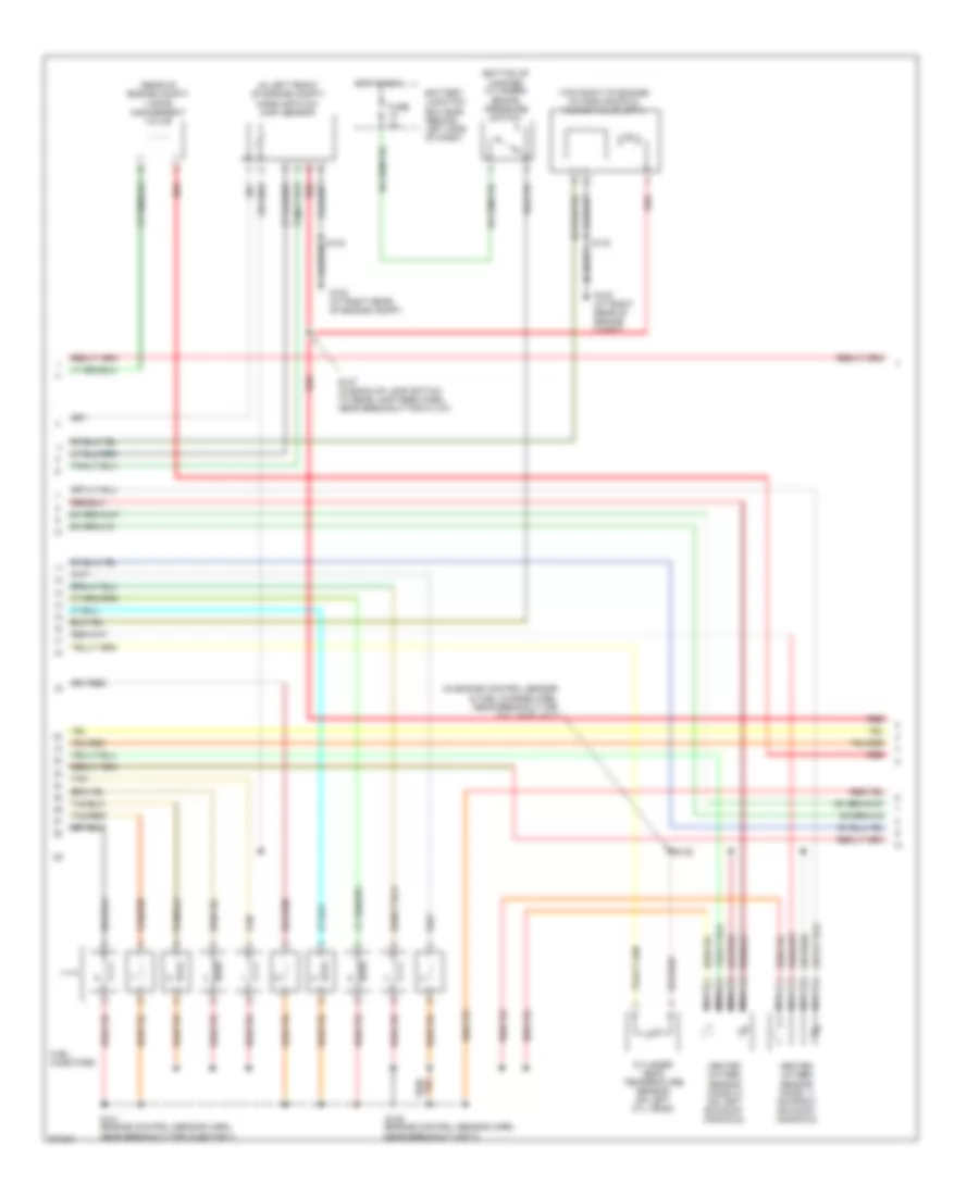
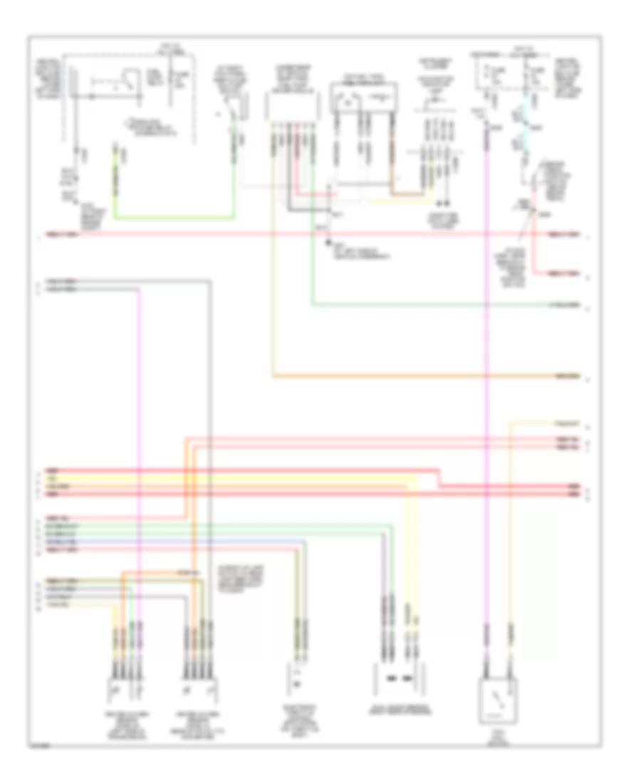
5.4L, Engine Performance Wiring Diagram (3 of 5) for Ford Cab & Chassis F350 Super Duty 2005
List of elements for 5.4L, Engine Performance Wiring Diagram (3 of 5) for Ford Cab & Chassis F350 Super Duty 2005:
- (in back-up lamp switch to rear lamp feed harn, near breakout for c1107) s127
- (in back-up light switch to rear light feed harn, near breakout for transmission)
- C175c
- Ho2s 12 htr
- Ho2s 12 input
- Ho2s 22 htr
- Ho2s 22 input
- Intermediate shaft speed sensor
- Iss sensor
- Oss sensor
- Output shaft speed sensor (at top of transmission)
- Powertrain control module (on left side of firewall)
- Pressure control (pc-a) solenoid
- Red
- Ref voltage
- S128 (in back-up light switch to rear light feed harn, near breakout for transmission)
- S129
- Shift sol a
- Shift sol b
- Shift sol c
- Shift sol d
- Shift sol e
- Shift solenoid pressure control a (sspc-a)
- Shift solenoid pressure control b (sspc-b)
- Shift solenoid pressure control c (sspc-c)
- Shift solenoid pressure control d (sspc-d)
- Shift solenoid pressure control e (sspc-e)
- Signal return
- Speed sensor assembly (top left side of transmission)
- Tcc sol
- Tft sensor
- Torqshift transmission
- Torque converter clutch solenoid
- Transmission fluid temperature sensor
- Transmission range sensor assembly (tr-p)
- Trs sensor
- Tss sensor
- Turbine shaft speed sensor
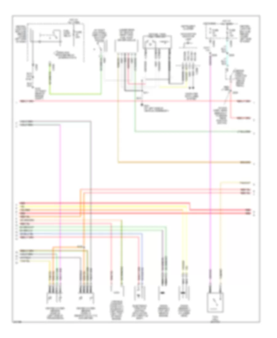
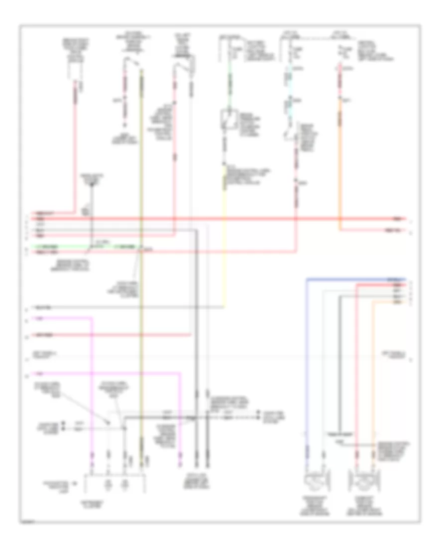
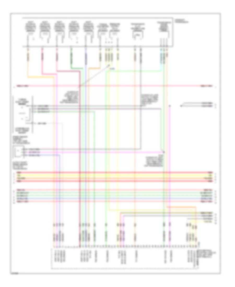
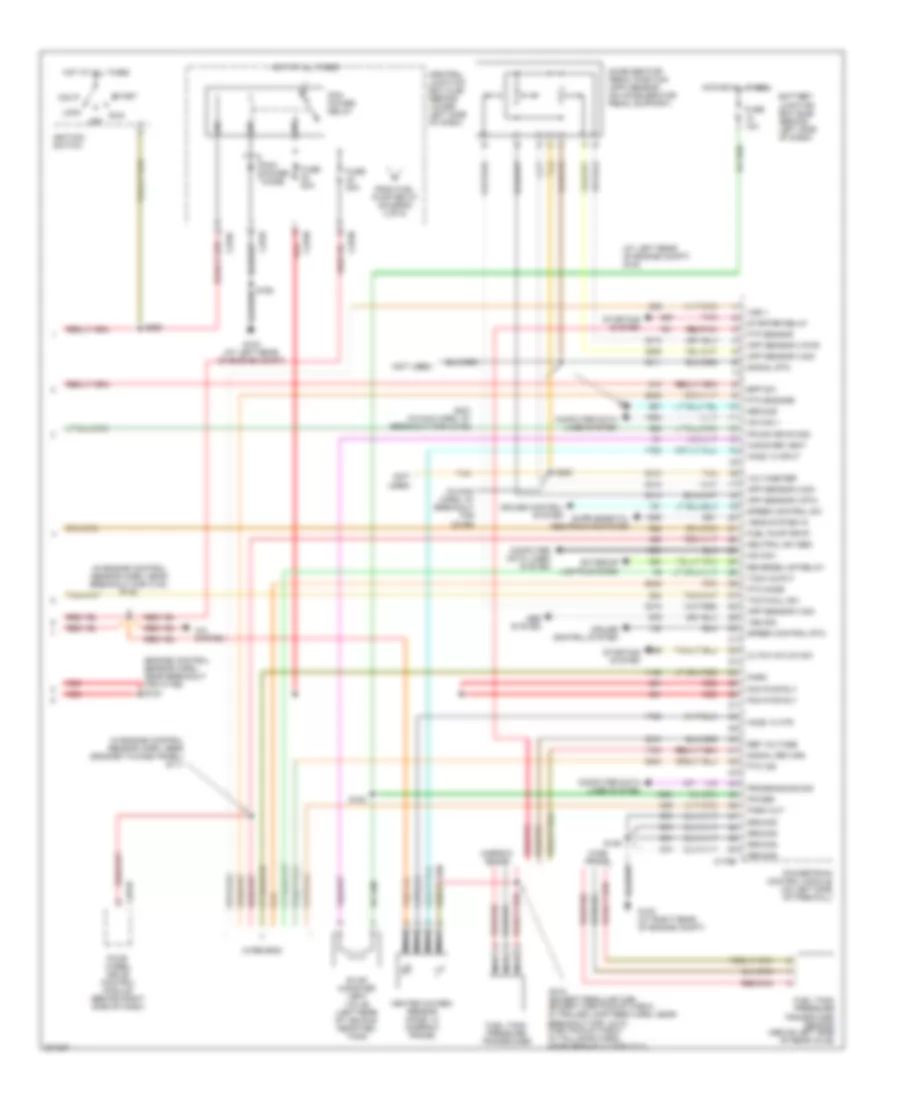
5.4L, Engine Performance Wiring Diagram (4 of 5) for Ford Cab & Chassis F350 Super Duty 2005
List of elements for 5.4L, Engine Performance Wiring Diagram (4 of 5) for Ford Cab & Chassis F350 Super Duty 2005:
- (at right kick panel) inertia fuel shut-off switch
- (in main harn, near breakout to brake pedal position switch)
- (on fuel tank) fuel tank unit
- (under rear of vehicle, near tank) fuel pump driver module
- Brake pedal position switch (above brake pedal)
- C270a
- C270f
- Central junction box (cjb) (behind lower left side of dash)
- Computer data lines system
- Electronic throttle control (etc) motor (on throttle body)
- From pcm power relay (diagram 5 of 5)
- Fuel lvl
- Fuel pump relay
- Fuse 10a
- Fuse 15a
- Fuse 20a
- G102 (at right rear of engine compt)
- G401 (at left side of vehicle underbody)
- Heated oxygen sensor (ho2s) 12 (rear of catalytic converter)
- Heated oxygen sensor (ho2s) 22 (left side of transmission)
- Hot at all times
- Hot in run
- Hs can +
- Hs can -
- Instrument cluster
- Knock sensor 1 (top right cylinder head)
- Knock sensor 2 (top left rear of engine)
- Malfunction indicator lamp
- Nca
- Red
- Return
- S106
- S138
- S205
- S208
- S235
- S411
- Tow/ haul switch
- Variable camshaft timing (vct) solenoid 2 (left bank) (left top of front engine)
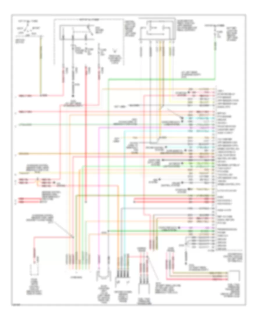
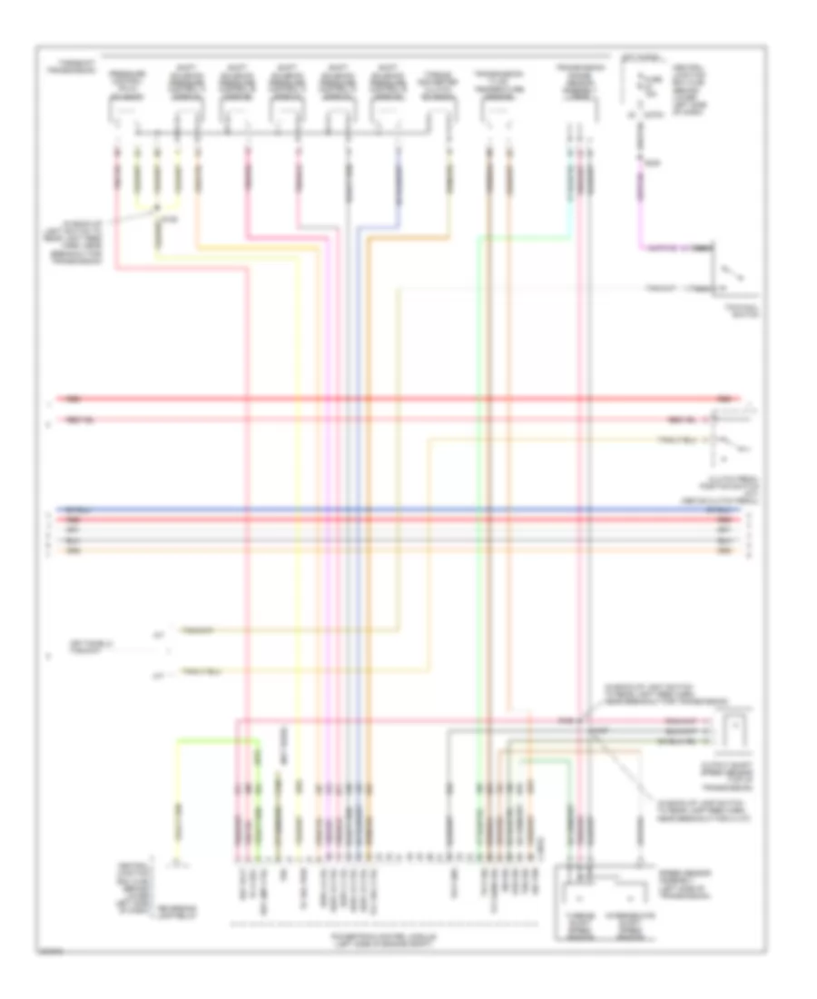
5.4L, Engine Performance Wiring Diagram (5 of 5) for Ford Cab & Chassis F350 Super Duty 2005
List of elements for 5.4L, Engine Performance Wiring Diagram (5 of 5) for Ford Cab & Chassis F350 Super Duty 2005:
- (at left rear of engine compt) g100
- (engine control sensor harn, near breakout for c1756) s123
- (in engine control sensor harn, near breakout for c140) s122
- (in engine control sensor harn, near grommet in dash panel) s111
- (in main harn, at breakout for c2186)
- (not used)
- (wire end)
- A/c system
- Abs system
- Acc
- Accelerator pedal position (app) sensor (on accelerator pedal support)
- App sensor 2 sig
- App sensor 3 pwr
- App sensor 3 rtn
- App sensor 3 sig
- Battery junction box (bjb) (behind left side of dash)
- Bpp sw
- C175b
- C270c
- C270f
- C270h
- C281b
- Canister vent
- Central junction box (cjb) (behind lower left side of dash)
- Cltch intlck sw
- Computer data lines system
- Cruise control system
- Evap canister vent valve (left rear of vehicle, near fuel tank)
- Exterior lights system
- Four- wheel drive control module (behind right side of dash)
- Fpump drvr mod
- From fuel pump relay (diagram 4 of 5)
- Ftp sensor
- Fuel pump drvr
- Fuel tank pressure transducer
- Fuel tank pressure transducer sensor (above left side of rear axle)
- Fuse 10a
- Fuse 20a
- G100 (at left rear of engine compt)
- G102 (at right rear of engine compt)
- Ground
- Heated oxygen sensor (ho2s) 13 (narrow frame)
- Ho2s 13 htr
- Ho2s 13 input
- Hot at all times
- Hs can +
- Hs can -
- Ignition switch
- Lock
- Narrow frame
- Nca
- Neutral sw sen
- Off
- Park
- Park out
- Pcm power diode
- Pcm power relay
- Pcm pwr rly
- Pnk
- Power
- Powertrain control module (on left side of firewall)
- Programming sig
- Pto engage
- Pto ind
- Pto mode
- Red
- Red/pnk
- Ref voltage
- Reverse lmp relay
- Run
- S106
- S162
- S164
- S221 (in main harn, at breakout for c2186)
- S223
- S258
- S412 (except regular cab) (in trailer lamp feed harn, near breakout for c410)
- Signal return
- Signal rtn
- Speed control rtn
- Speed control sw
- Start
- Starter relay
- Starting system
- Tach ouput
- Tan
- Tow/haul sw
- Vems system in
- Voltage ref
- Vss +
- Vss sig
- Wide frame
6.0L DIESEL
6.0L Diesel, Engine Performance Wiring Diagram (1 of 5) for Ford Cab & Chassis F350 Super Duty 2005
List of elements for 6.0L Diesel, Engine Performance Wiring Diagram (1 of 5) for Ford Cab & Chassis F350 Super Duty 2005:
- (at left rear of engine compt) g101
- (engine control sensor & fuel charge harn, near breakout to left rear of engine)
- (pins 11-21 not used)
- (pins 9-16 not used)
- Battery junction box (bjb) (left rear of engine compt)
- C1388a
- C1388b
- C1388c
- Can bus 2h
- Can bus 2l
- Cylinder id
- Drain wire
- Ficm to pcm connections (to diagram 5 of 5)
- Fuel delivery
- Fuel heater (left side of vehicle underbody
- Fuel heater relay
- Fuel inj 1 close gnd
- Fuel inj 1 close pwr
- Fuel inj 1 open gnd
- Fuel inj 1 open pwr
- Fuel inj 2 close gnd
- Fuel inj 2 close pwr
- Fuel inj 2 open gnd
- Fuel inj 2 open pwr
- Fuel inj 3 close gnd
- Fuel inj 3 close pwr
- Fuel inj 3 open gnd
- Fuel inj 3 open pwr
- Fuel inj 4 close gnd
- Fuel inj 4 close pwr
- Fuel inj 4 open gnd
- Fuel inj 4 open pwr
- Fuel inj 5 close gnd
- Fuel inj 5 close pwr
- Fuel inj 5 open gnd
- Fuel inj 5 open pwr
- Fuel inj 6 close gnd
- Fuel inj 6 close pwr
- Fuel inj 6 open gnd
- Fuel inj 6 open pwr
- Fuel inj 7 close gnd
- Fuel inj 7 close pwr
- Fuel inj 7 open gnd
- Fuel inj 7 open pwr
- Fuel inj 8 close gnd
- Fuel inj 8 close pwr
- Fuel inj 8 open gnd
- Fuel inj 8 open pwr
- Fuel injection control module (ficm) (top left rear of engine)
- Fuel injector 1 (top right side of engine)
- Fuel injector 2 (top left of engine)
- Fuel injector 3 (top right of engine)
- Fuel injector 4 (top left side of engine)
- Fuel injector 5 (top right rear of engine)
- Fuel injector 6 (top left rear of engine)
- Fuel injector 7 (top of right cylinder bank)
- Fuel injector 8 (left rear of engine)
- Fuel injector control module power relay
- Fuse 10a
- Fuse 15a
- Fuse 50a
- G100 (at left rear of engine compt)
- G110 (at top rear of engine)
- Ground
- Hot at all times
- Ignition
- Nca
- Pcm comm
- Power relay
- Power relay ctrl
- S102
- S120
- S194
- S195
- S250
6.0L Diesel, Engine Performance Wiring Diagram (2 of 5) for Ford Cab & Chassis F350 Super Duty 2005
List of elements for 6.0L Diesel, Engine Performance Wiring Diagram (2 of 5) for Ford Cab & Chassis F350 Super Duty 2005:
- (at left rear of engine compt)
- (ends in harness)
- (engine control sensor harn, near breakout to c128)
- (in back-up light switch to rear light feed harn, near breakout for automatic transmission module)
- (in engine control harn, near breakout for g101) s114
- (in engine control sensor harn, under battery junction box)
- (in main harn, near breakout for c218)
- (left rear of engine compt) g100
- (m/t)
- (m/t) (a/t)
- (not used)
- A/c press sw
- A/c relay
- A/c system
- Abs system
- Acc
- Accelerator pedal position sensor (on accelerator pedal support)
- Apps 1 sig
- Apps 2 rtn
- Apps 2 sig
- Apps 3 sig
- Aps2
- Baro press
- Barometric absolute pressure sensor (behind left side of dash)
- Battery junction box (bjb) (left rear of engine compt)
- Bcpsw
- Brake press sw
- C1381b
- C270a
- C270c
- C270f
- C270h
- Central junction box (cjb) (behind lower left side of dash)
- Cltch ped deact
- Cruise control
- Cto
- Customer acc
- Dlc can h
- Dlc can l
- Fuel pump (near left side of transmission)
- Fuel pump relay
- Fuse 10a
- Fuse 20a
- G100
- G101 (at left rear of engine compt)
- Gen/batt
- Ground
- Hot at all times
- Iat sensor
- Ignition
- Ignition switch
- Inertia fuel shutoff switch (at right kick panel)
- Inertia sw
- Intake air temperature sensor (late production) (left side of engine compt, behind air cleaner)
- Lock
- Maf sensor
- Manifold absolute pressure sensor (at rear of firewall)
- Map sensor
- Mass air- flow sensor (in air intake tube)
- Nca
- Off
- Park brake
- Pcm power diode
- Pcm power relay
- Pnk
- Powertrain control module (pcm) (left side of engine compt)
- Prog sig
- Pto
- Pto rpm
- Pto vref
- Red
- Ref voltage
- Run
- S106
- S117
- S118 (in engine control harn, near breakout for powertrain control module)
- S123 (in engine control sensor harn, near breakout for c1298)
- S139
- S150
- S162
- S170
- S182
- S221 (main harn, at breakout for c2186)
- S223
- S234 (in body main harn, near c278)
- S250
- S258
- Signal return
- Speed ctrl sw
- Start
- Start intlck
- Start rly cntrl
- Starting system
- Stoplamp sw
- Tan
- Tow/haul sw
- Tr0-n2
- Tr0-p
- Vbatt
- Vso
- Vss
- Water in fuel
6.0L Diesel, Engine Performance Wiring Diagram (3 of 5) for Ford Cab & Chassis F350 Super Duty 2005
List of elements for 6.0L Diesel, Engine Performance Wiring Diagram (3 of 5) for Ford Cab & Chassis F350 Super Duty 2005:
- (behind right side of dash) four wheel drive control module
- (engine control sensor & fuel charge harn, at breakout for c1381c)
- (engine control sensor harn, at breakout for g100)
- (in engine control sensor harn, near breakout to c135)
- (in main harn, at breakout for (dlc)) s220
- (in main harn, near breakout for (dlc)) s213
- (main harn, at breakout for instrument cluster)
- (on left frame rail) water- in-fuel sensor
- (on park brake assembly) parking brake switch
- (w/ drl)
- Battery junction box (bjb) (left rear of engine compt)
- Brake pedal position switch (above brake pedal)
- Brake pressure switch (on brake master cylinder)
- C220a
- C220b
- C270a
- C281b
- Camshaft position sensor (on lower front center of engine)
- Central junction box (cjb) (behind lower left side of dash)
- Computer data lines system
- Crankshaft position sensor (lower right side of engine)
- Data link connector (behind left side of dash)
- Fuse 10a
- Fuse 2a
- G300 (under left side of dash)
- Headlights system (w/ drl)
- Hot at all times
- Hot in run
- Hs can (+)
- Hs can (-)
- Instrument cluster
- Malfunction indicator lamp
- Nca
- Red
- S110 (engine control harn, near breakout for powertrain control module)
- S112 (engine control harn, near breakout for powertrain control module)
- S142
- S174
- S197
- S205
- S208
- S271
- S278
- Sensor harn, near breakout to g300) s140
6.0L Diesel, Engine Performance Wiring Diagram (4 of 5) for Ford Cab & Chassis F350 Super Duty 2005
List of elements for 6.0L Diesel, Engine Performance Wiring Diagram (4 of 5) for Ford Cab & Chassis F350 Super Duty 2005:
- (a/t)
- (in back-up lamp switch to rear lamp feed harn, near breakout for c1107)
- (in back-up light switch to rear light feed harn, near breakout for transmission)
- (not used)
- A/t
- C1381e
- C270a
- Central junction box (cjb) (behind lower left side of dash)
- Clutch pedal position switch (m/t) (above clutch pedal)
- Fuse 15a
- Hot in run
- Intermediate shaft speed sensor
- Iss sig
- M/t
- Nca
- Oss sig
- Output shaft speed sensor (top of transmission)
- Pc sol pwr
- Pc-a sol
- Powertrain control module (left side of engine compt)
- Pressure control (pc-a) solenoid
- Red
- Ref volt
- Rev lmp ctrl
- Reversing lamp relay
- S127
- S128
- S129
- S235
- Shift solenoid pressure control a (sspc-a)
- Shift solenoid pressure control b (sspc-b)
- Shift solenoid pressure control c (sspc-c)
- Shift solenoid pressure control d (sspc-d)
- Shift solenoid pressure control e (sspc-e)
- Sig trn
- Speed sensor assembly (left side of transmission)
- Sspc-a crl
- Sspc-b ctrl
- Sspc-c crl
- Sspc-d ctrl
- Sspc-e ctrl
- Tcc sol ctrl
- Tft sens sig
- Torqshift transmission
- Torque converter clutch solenoid
- Tow/haul switch
- Tr-p gnd
- Tr-p sig
- Transmission fluid temperature sensor
- Transmission range sensor assembly (tr-p)
- Tro
- Tss sig
- Turbine shaft speed sensor
6.0L Diesel, Engine Performance Wiring Diagram (5 of 5) for Ford Cab & Chassis F350 Super Duty 2005
List of elements for 6.0L Diesel, Engine Performance Wiring Diagram (5 of 5) for Ford Cab & Chassis F350 Super Duty 2005:
- (engine control sensor & fuel charge harn, near breakout for c1064)
- (not used)
- (top rear center of engine) injection pressure regulator
- (top right front of engine) glow plug control module
- Act sensor
- Battery
- C1301a
- C1301b
- C1381t
- Can bus 2h
- Can bus 2l
- Charge
- Charge (2nd)
- Ckp sensor
- Cmp sensor
- Coolant temp
- Cooling fan
- Cooling fans system
- Ebp sensor
- Egr temp sen
- Egr temperature sensor (early production) (top front of engine)
- Egr valve
- Egr valve actuator (at top of engine)
- Engine coolant temperature sensor (on front of engine)
- Engine oil temperature sensor (left right of engine)
- Eot sensor
- Exhaust back pressure sensor (left front of engine)
- Fan clutch
- Ficm comm
- Ficm cyl id
- Ficm delivery
- Ficm to pcm connections (from diagram 1 of 5)
- Fuse link f 12 gauge gray
- Fuse linkg 12 gauge gray
- Generator
- Glow plug
- Glow plug 1
- Glow plug 2
- Glow plug 3
- Glow plug 4
- Glow plug 5
- Glow plug 6
- Glow plug 7
- Glow plug 8
- Glow plug sys
- Ground
- Hot at all times
- Icp sensor
- Ignition
- Injection control pressure sensor (top left rear of engine)
- Ipr control
- Left glow plug bank
- Manifold air temperature sensor (top left front of engine)
- Nca
- Pcm control
- Pcm monitor
- Powertrain control module (pcm) (left side of engine compt)
- Red
- Ref voltage
- Right glow plug bank
- S147
- S190
- S192
- S193 (in engine harn, top left of engine)
- Secondary generator
- Signal return
- Turbo act
- Variable geometric turbo actuator
- W/ dual generators
6.8L
6.8L, Engine Performance Wiring Diagram (1 of 5) for Ford Cab & Chassis F350 Super Duty 2005
List of elements for 6.8L, Engine Performance Wiring Diagram (1 of 5) for Ford Cab & Chassis F350 Super Duty 2005:
- (in engine control sensor & fuel charge harn, near breakout for c175a)
- A/c clutch rly
- A/c press sw
- A/c system
- Brake pressure sw
- C175a
- Camshaft position sensor (on front of left cylinder head)
- Ckp sensor +
- Ckp sensor -
- Cmp sensor
- Coil on plug
- Coil on plug 1
- Coil on plug 10
- Coil on plug 2
- Coil on plug 3
- Coil on plug 4
- Coil on plug 5
- Coil on plug 6
- Coil on plug 7
- Coil on plug 8
- Coil on plug 9
- Crankshaft position sensor (on lower front center of engine)
- Cyl head temp
- Etc motor
- Fuel inj 1
- Fuel inj 10
- Fuel inj 2
- Fuel inj 3
- Fuel inj 4
- Fuel inj 5
- Fuel inj 6
- Fuel inj 7
- Fuel inj 8
- Fuel inj 9
- Fuel rail press sen
- Fuel rail temp sens
- Ho2s 11 htr
- Ho2s 11 input
- Ho2s 21 htr
- Ho2s 21 input
- Iat sensor
- Ignition transformer capacitor 1 (top right front of engine)
- Ignition transformer capacitor 2 (top front of left cylinder head)
- Imtv cntrl
- Injection pressure sensor (ips) (top left center of intake manifold)
- Knock sensor 1 +
- Knock sensor 1 -
- Knock sensor 2 +
- Knock sensor 2 -
- Maf sensor
- Nca
- Powertrain control module (on left side of firewall)
- Reference voltage
- S130
- S135
- S145
- S147 (in engine control sensor & fuel charge harn, near breakout for c1073)
- Shield drain
- Signal return
- Tan
- Tan/red
- Throttle position sensor (top center of engine)
- Tps 1 sig
- Tps 2 sig
- Tps ref
- Tps sig return
- Vapor man valve
6.8L, Engine Performance Wiring Diagram (2 of 5) for Ford Cab & Chassis F350 Super Duty 2005
List of elements for 6.8L, Engine Performance Wiring Diagram (2 of 5) for Ford Cab & Chassis F350 Super Duty 2005:
- (bottom of master cylinder) brake pressure switch
- (engine control sensor harn, near breakout cop 3)
- (engine control sensor harn, near breakout for injector 7)
- (in engine control sensor & fuel charge harn, near breakout for coil on plug 7)
- (in left front of engine compt) mass air flow (maf) sensor
- (rear of engine compt) vapor management valve
- (top right of engine) intake manifold tuning valve (imtv)
- Battery junction box (bjb) (behind left side of dash)
- Cylinder head temperature sensor (on left cyl head)
- Fuel injectors
- Fuse 2a
- G102 (at right rear of engine compt)
- Heated oxygen sensor (ho2s) 11 (on right exhaust manifold)
- Heated oxygen sensor (ho2s) 21 (on left exhaust manifold)
- Hot in run
- Nca
- Red
- S127 (in back-up lamp switch to rear lamp feed harn, near breakout for c1107)
- S131
- S132
- S136
- S143
- Tan
- Tan/red
6.8L, Engine Performance Wiring Diagram (3 of 5) for Ford Cab & Chassis F350 Super Duty 2005
List of elements for 6.8L, Engine Performance Wiring Diagram (3 of 5) for Ford Cab & Chassis F350 Super Duty 2005:
- (in back-up lamp switch to rear lamp feed harn, near breakout for c1107) s127
- (in back-up light switch to rear light feed harn, near breakout for transmission)
- C175c
- Ho2s 12 htr
- Ho2s 12 input
- Ho2s 22 htr
- Ho2s 22 input
- Intermediate shaft speed sensor
- Iss sensor
- Oss sensor
- Output shaft speed sensor (at top of transmission)
- Powertrain control module (on left side of firewall)
- Pressure control (pc-a) solenoid
- Red
- Ref voltage
- S128 (in back-up light switch to rear light feed harn, near breakout for transmission)
- S129
- Shift sol a
- Shift sol b
- Shift sol c
- Shift sol d
- Shift sol e
- Shift solenoid pressure control a (sspc-a)
- Shift solenoid pressure control b (sspc-b)
- Shift solenoid pressure control c (sspc-c)
- Shift solenoid pressure control d (sspc-d)
- Shift solenoid pressure control e (sspc-e)
- Signal return
- Speed sensor assembly (top left side of transmission)
- Tcc sol
- Tft sensor
- Torqshift transmission
- Torque converter clutch solenoid
- Transmission fluid temperature sensor
- Transmission range sensor assembly (tr-p)
- Trs sensor
- Tss sensor
- Turbine shaft speed sensor
6.8L, Engine Performance Wiring Diagram (4 of 5) for Ford Cab & Chassis F350 Super Duty 2005
List of elements for 6.8L, Engine Performance Wiring Diagram (4 of 5) for Ford Cab & Chassis F350 Super Duty 2005:
- (at right kick panel) inertia fuel shut-off switch
- (in back up lamp switch to rear lamp feed harn, near breakout to c350a)
- (in main harn, near breakout to brake pedal position switch)
- (on fuel tank) fuel tank unit
- (under rear of vehicle, near tank) fuel pump driver module
- Brake pedal position switch (above brake pedal)
- C270a
- C270f
- Central junction box (cjb) (behind lower left side of dash)
- Computer data lines system
- Dual knock sensor (right rear of engine)
- Electronic throttle control (etc) motor (on throttle body)
- From pcm power relay (diagram 5 of 5)
- Fuel lvl
- Fuel pump relay
- Fuse 10a
- Fuse 15a
- Fuse 20a
- G102 (at right rear of engine compt)
- G401 (at left side of vehicle underbody)
- Heated oxygen sensor (ho2s) 12 (rear of catalytic converter)
- Heated oxygen sensor (ho2s) 22 (left side of transmission)
- Hot at all times
- Hot in run
- Hs can +
- Hs can -
- Instrument cluster
- Malfunction indicator lamp
- Nca
- Red
- Return
- S106
- S138
- S205
- S208
- S235
- S411
- Tow/ haul switch
6.8L, Engine Performance Wiring Diagram (5 of 5) for Ford Cab & Chassis F350 Super Duty 2005
List of elements for 6.8L, Engine Performance Wiring Diagram (5 of 5) for Ford Cab & Chassis F350 Super Duty 2005:
- (at left rear of engine compt) g100
- (engine control sensor harn, near breakout for c1756) s123
- (in engine control sensor harn, near breakout for c140) s122
- (in engine control sensor harn, near grommet in dash panel) s111
- (in main harn, at breakout for c2186)
- (not used)
- (wire end)
- A/c system
- Abs system
- Acc
- Accelerator pedal position (app) sensor (on accelerator pedal support)
- App sensor 2 sig
- App sensor 3 pwr
- App sensor 3 rtn
- App sensor 3 sig
- Battery junction box (bjb) (behind left side of dash)
- Bpp sw
- C175b
- C270c
- C270f
- C270h
- C281b
- Canister vent
- Central junction box (cjb) (behind lower left side of dash)
- Cltch intlck sw
- Computer data lines system
- Cruise control system
- Evap canister vent valve (left rear of vehicle, near fuel tank)
- Exterior lights system
- Four- wheel drive control module (behind right side of dash)
- Fpump drvr mod
- From fuel pump relay (diagram 4 of 5)
- Ftp sensor
- Fuel pump drvr
- Fuel tank pressure transducer
- Fuel tank pressure transducer sensor (above left side of rear axle)
- Fuse 10a
- Fuse 20a
- G100 (at left rear of engine compt)
- G102 (at right rear of engine compt)
- Ground
- Heated oxygen sensor (ho2s) 13 (narrow frame)
- Ho2s 13 htr
- Ho2s 13 input
- Hot at all times
- Hs can +
- Hs can -
- Ignition switch
- Lock
- Narrow frame
- Nca
- Neutral sw sen
- Off
- Park
- Park out
- Pcm power diode
- Pcm power relay
- Pcm pwr rly
- Pnk
- Power
- Powertrain control module (on left side of firewall)
- Programming sig
- Pto engage
- Pto ind
- Pto mode
- Red
- Red/pnk
- Ref voltage
- Reverse lmp relay
- Run
- S106
- S162
- S164
- S221 (in main harn, at breakout for c2186)
- S223
- S258
- S412 (except regular cab) (except f450 pickup w/box: in trailer lamp feed harn, near breakout for c410) (f450 pickup w/box: in taillamps harn, near breakout for c311)
- Signal return
- Signal rtn
- Speed control rtn
- Speed control sw
- Start
- Starter relay
- Starting system
- Tach ouput
- Tan
- Tow/haul sw
- Vems system in
- Voltage ref
- Vss +
- Vss sig
- Wide frame

 Čeština
 Dansk
Dansk Deutsch
 Ελληνικά
 English
 English
 Español
 Suomi
Suomi Français
 Français
 עברית
עברית Hrvatski
 Magyar
 日本語
日本語 한국어
한국어 Nederlands
 Polski
 Português
 Português
 Română
 Русский
 Slovenčina
 Slovenščina
 Svenska
 Türkçe
 中文 (中国)