AIR CONDITIONING
2.2L
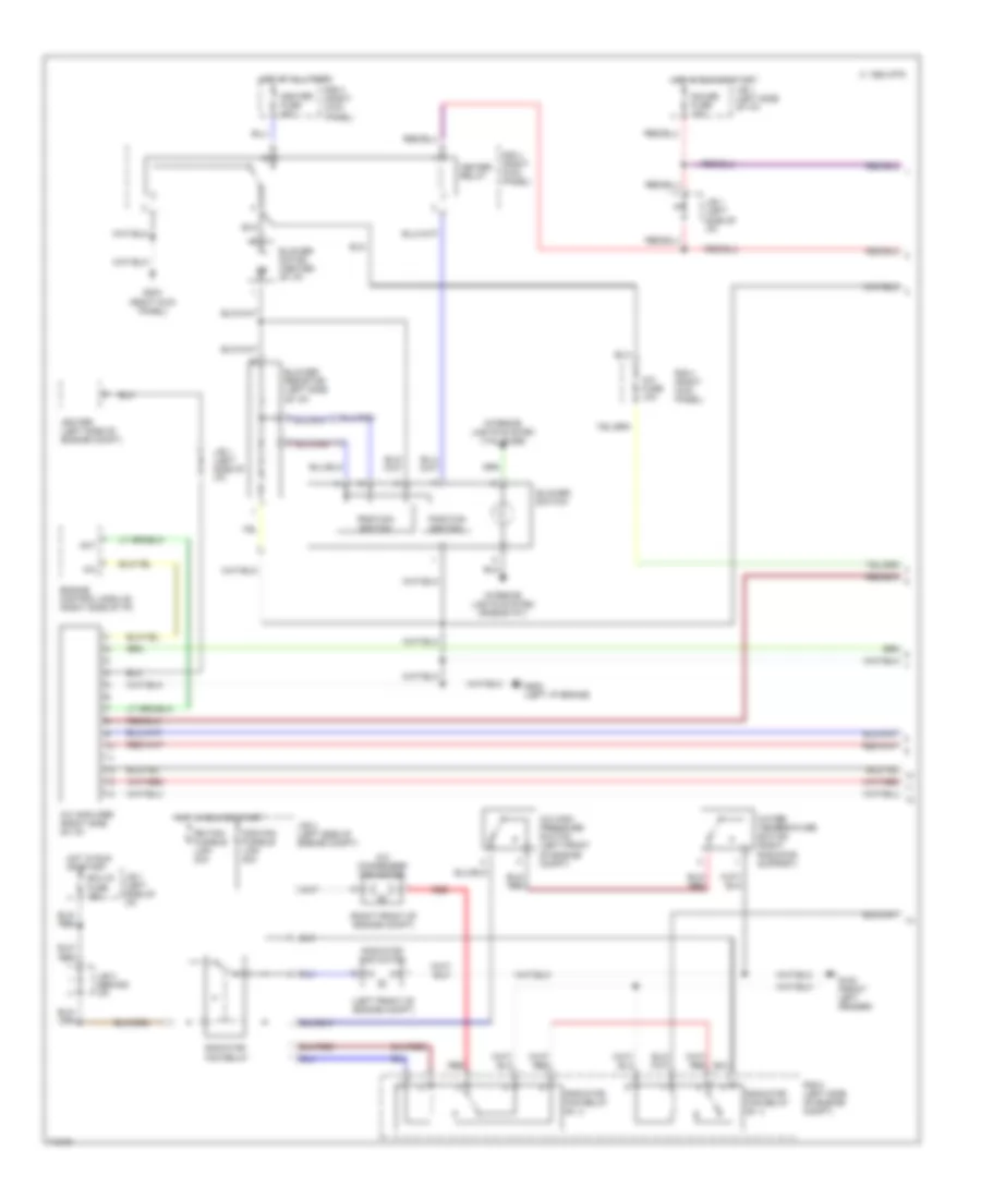
2.2L, A/C Wiring Diagram, Lever Control Type for Toyota Camry SE 1996
 https://portal-diagnostov.com/license.html
Automotive Electricians Portal FZCO
Automotive Electricians Portal FZCO
https://portal-diagnostov.com/license.html
https://portal-diagnostov.com/license.html
Automotive Electricians Portal FZCO
Automotive Electricians Portal FZCO
List of elements for 2.2L, A/C Wiring Diagram, Lever Control Type for Toyota Camry SE 1996:
- (left front of engine compt)
- (right front of engine compt)
- 1994 vftc c
- A/c
- A/c amplifier (right side of i/p)
- A/c condenser fan motor
- A/c dual pressure switch (left front of engine compt)
- A/c evaporator temperature sensor (right side of i/p)
- A/c fuse 10a
- A/c high pressure switch (left front of engine compt)
- A/c magnetic clutch & lock sensor (right front of engine)
- A/c magnetic clutch relay
- A/c switch (center of i/p)
- A15
- Act
- Air vent mode control servo motor (center of i/p)
- Air vent mode control switch (center of i/p)
- B/l
- Blower motor (center of i/p)
- Blower resistor (left side of i/p)
- Blower switch
- Cds fan fusible link 30a
- Control circuit
- Control switch
- D12
- Def
- Ecu-ig fuse 15a
- Engine control module (right side of i/p)
- F/d
- Face
- Foot
- G100 (front left fender)
- G202 (left i/p brace)
- G203 (right kick panel)
- Gauge fuse 10a
- Heater fuse 40a
- Heater relay
- Hot at all times
- Hot in run or start
- Igniter (left side of engine compt)
- Interior lights system (rheostat)
- Interior lights system (tail fuse)
- J/b 1 (left side of i/p)
- J/b 2 (left side of engine compt)
- J/b 3 (behind i/p)
- J/c 1 (left side of i/p)
- Off
- R/b 4 (right kick panel)
- R/b 5 (left side of engine compt)
- Radiator fan motor
- Radiator fan relay
- Radiator fan relay n0. 3
- Radiator fan relay no. 2
- Rdi fan fusible link 30a
- Red
- Water temperature switch (right radiator support)
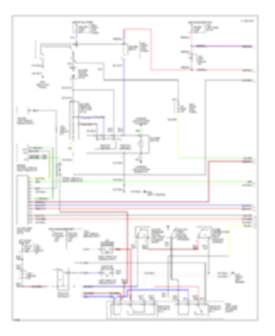
2.2L, A/C Wiring Diagram, Push Control Type (1 of 2) for Toyota Camry SE 1996
List of elements for 2.2L, A/C Wiring Diagram, Push Control Type (1 of 2) for Toyota Camry SE 1996:
- (left front of engine compt)
- (right front of engine compt)
- 1994 vftc c
- A/c
- A/c amplifer (right side of i/p)
- A/c condenser fan motor
- A/c fuse 10a
- A/c high pressure switch (left front of engine compt)
- Act
- Blower motor (center of i/p)
- Blower resistor (left side of i/p)
- Blower switch
- Cds fan fusible link 30a
- Ecu-ig fuse 15a
- Engine control module (right side of i/p)
- G100 (front left fender)
- G202 (left i/p brace)
- G203 (right kick panel)
- Gauge fuse 10a
- Heater fuse 40a
- Heater relay
- Hot at all times
- Hot in run or start
- Igniter (left side of engine compt)
- Interior lights system (rheostat)
- Interior lights system (tail fuse)
- J/b 1 (left side of i/p)
- J/b 2 (left side of engine compt)
- J/b 3 (behind i/p)
- Position switch
- R/b 4 (right kick panel)
- R/b 5 (left side of engine compt)
- Radiator fan motor
- Radiator fan relay
- Radiator fan relay n0. 2
- Radiator fan relay n0. 3
- Rdi fan fusible link 30a
- Red
- Water temperature switch (right radiator support)
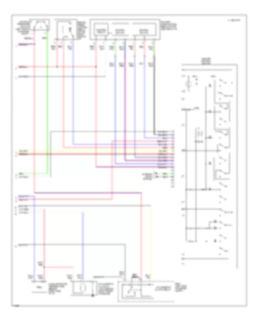
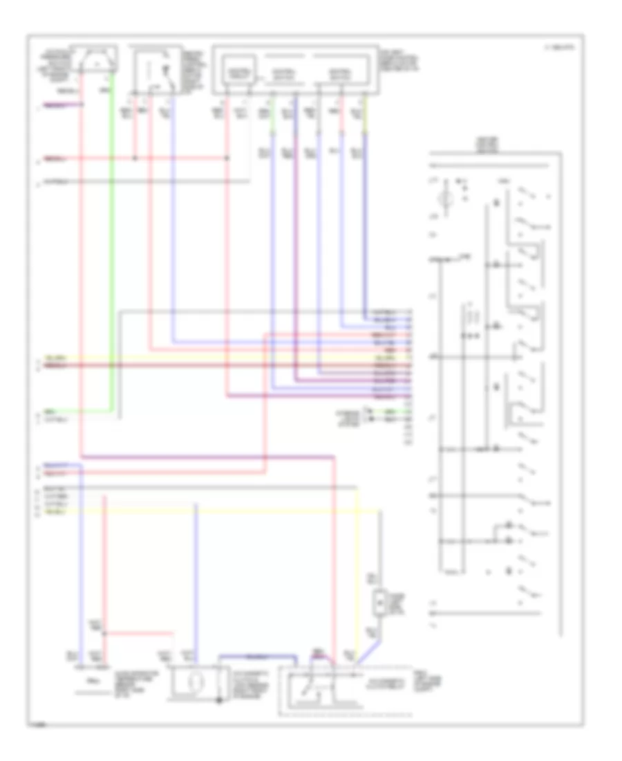
2.2L, A/C Wiring Diagram, Push Control Type (2 of 2) for Toyota Camry SE 1996
List of elements for 2.2L, A/C Wiring Diagram, Push Control Type (2 of 2) for Toyota Camry SE 1996:
- 1994 vftc c
- A/c dual pressure switch (left front of engine compt)
- A/c evaporator temperature sensor (right side of i/p)
- A/c magnetic clutch & lock sensor (right front of engine)
- A/c magnetic clutch relay
- Air vent mode control servo motor (center of i/p)
- Control circuit
- Control switch
- Heater control switch
- Interior lights system
- R/b 5 (left side of engine compt)
- Recirc/ fresh control servo motor (right side of i/p)
- Red
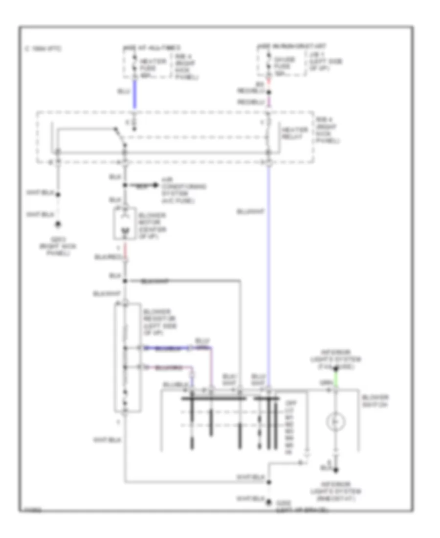
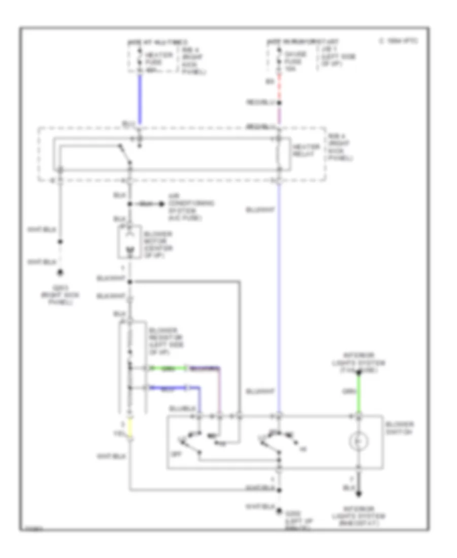
Heater Wiring Diagram, Lever Control Type for Toyota Camry SE 1996
List of elements for Heater Wiring Diagram, Lever Control Type for Toyota Camry SE 1996:
- 1994 vftc c
- Air conditioning system (a/c fuse)
- Blower motor (center of i/p)
- Blower resistor (left side of i/p)
- Blower switch
- G202 (left i/p brace)
- G203 (right kick panel)
- Gauge fuse 10a
- Heater fuse 40a
- Heater relay
- Hot at all times
- Hot in run or start
- Interior lights system (rheostat)
- Interior lights system (tail fuse)
- J/b 1 (left side of i/p)
- Off
- R/b 4 (right kick panel)
Heater Wiring Diagram, Push Control Type for Toyota Camry SE 1996
List of elements for Heater Wiring Diagram, Push Control Type for Toyota Camry SE 1996:
- 1994 vftc c
- Air conditioning system (a/c fuse)
- Blower motor (center of i/p)
- Blower resistor (left side of i/p)
- Blower switch
- G202 (left i/p brace)
- G203 (right kick panel)
- Gauge fuse 10a
- Heater fuse 40a
- Heater relay
- Hot at all times
- Hot in run or start
- Interior lights system (rheostat)
- Interior lights system (tail fuse)
- J/b 1 (left side of i/p)
- Off lo m1 m2 m3 m4 m5 hi
- R/b 4 (right kick panel)
3.0L
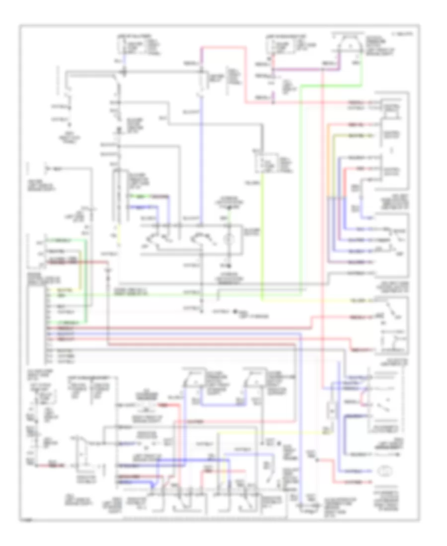
3.0L, A/C Wiring Diagram, Lever Control Type for Toyota Camry SE 1996
List of elements for 3.0L, A/C Wiring Diagram, Lever Control Type for Toyota Camry SE 1996:
- (1995 only)
- (1996) (1995)
- (left front of engine compt)
- (right front of engine compt)
- 1994 vftc c
- A/c
- A/c amplifier (right side of i/p)
- A/c condenser fan motor
- A/c dual pressure switch (left front of engine compt)
- A/c evaporator temperature sensor (right side of i/p)
- A/c fuse 10a
- A/c high pressure switch (left front of engine compt)
- A/c magnetic clutch & lock sensor (right front of engine)
- A/c magnetic clutch relay
- A/c switch (center of i/p)
- A15
- Act
- Air vent mode control servo motor (center of i/p)
- Air vent mode control switch (center of i/p)
- B/l
- Blower motor (center of i/p)
- Blower resistor (left side of i/p)
- Blower switch
- Cds fan fusible link 30a
- Control circuit
- Control switch
- Coolant temp switch (center of engine)
- D12
- Def
- Diode (right side of i/p)
- Ecu-ig fuse 15a
- Engine control module (right side of i/p)
- F/d
- Face
- Foot
- G100 (front left fender)
- G202 (left i/p brace)
- G203 (right kick panel)
- Gauge fuse 10a
- Heater fuse 40a
- Heater relay
- Hot at all times
- Hot in run or start
- Igniter (left side of engine compt)
- Interior lights system (rheostat)
- Interior lights system (tail fuse)
- J/b 1 (left side of i/p)
- J/b 2 (left side of engine compt)
- J/b 3 (behind i/p)
- J/c 1 (left side of i/p)
- Off
- R/b 4 (right kick panel)
- R/b 5 (left side of engine compt)
- Radiator fan motor
- Radiator fan relay
- Radiator fan relay n0. 3
- Radiator fan relay no. 2
- Rdi fan fusible link 30a
- Red
- Water temperature switch (right radiator support)
3.0L, A/C Wiring Diagram, Push Control Type (1 of 2) for Toyota Camry SE 1996
List of elements for 3.0L, A/C Wiring Diagram, Push Control Type (1 of 2) for Toyota Camry SE 1996:
- (1995 only)
- (1995) (1996)
- (left front of engine compt)
- (right front of engine compt)
- 1994 vftc c
- A/c
- A/c amplifer (right side of i/p)
- A/c condenser fan motor
- A/c fuse 10a
- A/c high pressure switch (left front of engine compt)
- Act
- Blower motor (center of i/p)
- Blower resistor (left side of i/p)
- Blower switch
- Cds fan fusible link 30a
- Coolant temp switch (center of engine)
- Diode (right side of i/p)
- Ecu-ig fuse 15a
- Engine control module (right side of i/p)
- G100 (front left fender)
- G202 (left i/p brace)
- G203 (right kick panel)
- Gauge fuse 10a
- Heater fuse 40a
- Heater relay
- Hot at all times
- Hot in run or start
- Igniter (left side of engine compt)
- Interior lights system (rheostat)
- Interior lights system (tail fuse)
- J/b 1 (left side of i/p)
- J/b 2 (left side of engine compt)
- J/b 3 (behind i/p)
- Position switch
- R/b 4 (right kick panel)
- R/b 5 (left side of engine compt)
- Radiator fan motor
- Radiator fan relay
- Radiator fan relay n0. 2
- Radiator fan relay n0. 3
- Rdi fan fusible link 30a
- Red
- Water temperature switch (right radiator support)
3.0L, A/C Wiring Diagram, Push Control Type (2 of 2) for Toyota Camry SE 1996
List of elements for 3.0L, A/C Wiring Diagram, Push Control Type (2 of 2) for Toyota Camry SE 1996:
- 1994 vftc c
- A/c dual pressure switch (left front of engine compt)
- A/c evaporator temperature sensor (right side of i/p)
- A/c magnetic clutch & lock sensor (right front of engine)
- A/c magnetic clutch relay
- Air vent mode control servo motor (center of i/p)
- Control circuit
- Control switch
- Diode (left side of i/p)
- Heater control switch
- Interior lights system
- R/b 5 (left side of engine compt)
- Recirc/ fresh control servo motor (right side of i/p)
- Red
Heater Wiring Diagram, Lever Control Type for Toyota Camry SE 1996
List of elements for Heater Wiring Diagram, Lever Control Type for Toyota Camry SE 1996:
- 1994 vftc c
- Air conditioning system (a/c fuse)
- Blower motor (center of i/p)
- Blower resistor (left side of i/p)
- Blower switch
- G202 (left i/p brace)
- G203 (right kick panel)
- Gauge fuse 10a
- Heater fuse 40a
- Heater relay
- Hot at all times
- Hot in run or start
- Interior lights system (rheostat)
- Interior lights system (tail fuse)
- J/b 1 (left side of i/p)
- Off
- R/b 4 (right kick panel)
Heater Wiring Diagram, Push Control Type for Toyota Camry SE 1996
List of elements for Heater Wiring Diagram, Push Control Type for Toyota Camry SE 1996:
- 1994 vftc c
- Air conditioning system (a/c fuse)
- Blower motor (center of i/p)
- Blower resistor (left side of i/p)
- Blower switch
- G202 (left i/p brace)
- G203 (right kick panel)
- Gauge fuse 10a
- Heater fuse 40a
- Heater relay
- Hot at all times
- Hot in run or start
- Interior lights system (rheostat)
- Interior lights system (tail fuse)
- J/b 1 (left side of i/p)
- Off lo m1 m2 m3 m4 m5 hi
- R/b 4 (right kick panel)

 Čeština
 Dansk
Dansk Deutsch
 Ελληνικά
 English
 English
 Español
 Suomi
Suomi Français
 Français
 עברית
עברית Hrvatski
 Magyar
 日本語
日本語 한국어
한국어 Nederlands
 Polski
 Português
 Português
 Română
 Русский
 Slovenčina
 Slovenščina
 Svenska
 Türkçe
 中文 (中国)