CRUISE CONTROL
4.2L
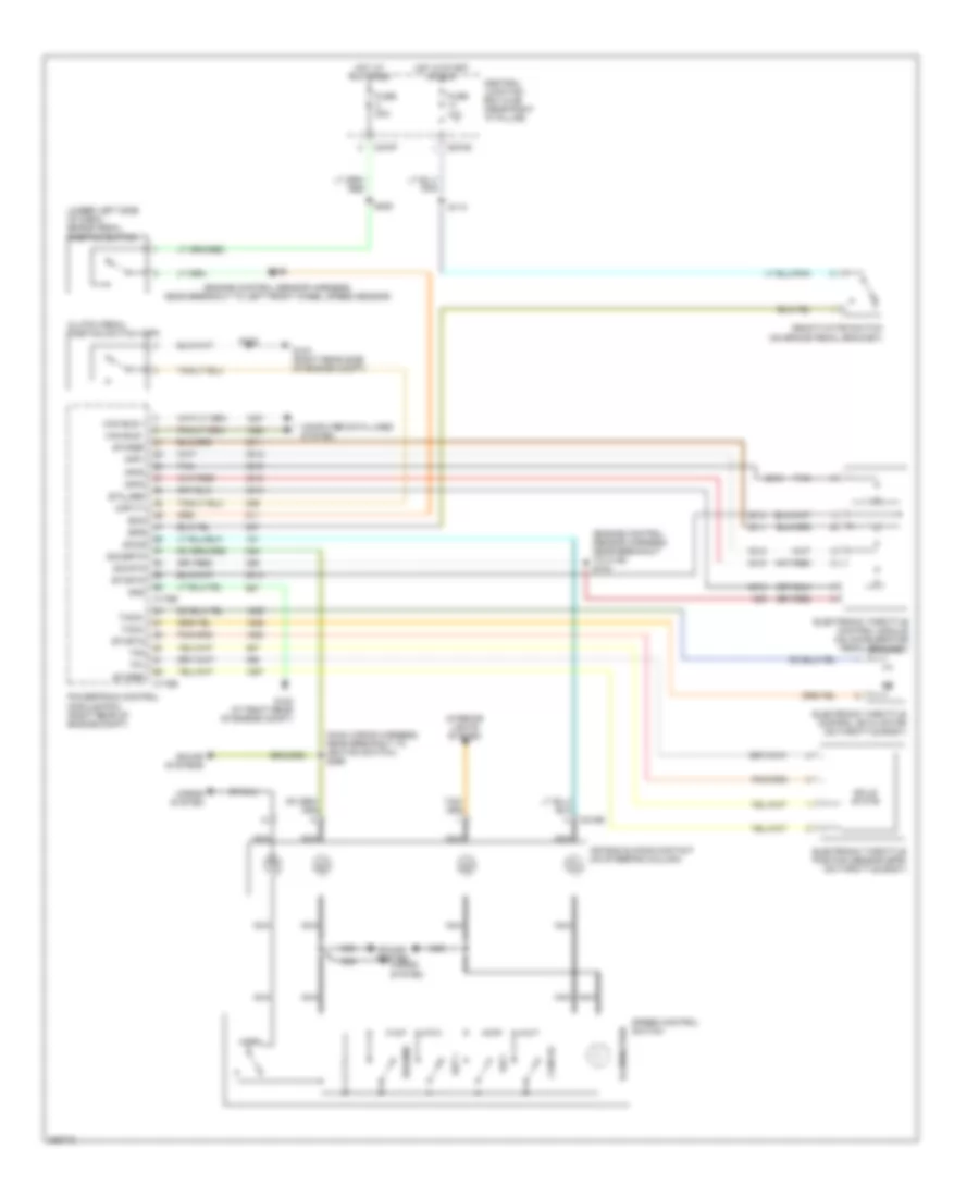
4.2L, Cruise Control Wiring Diagram for Ford Pickup F150 2006
 https://portal-diagnostov.com/license.html
Automotive Electricians Portal FZCO
Automotive Electricians Portal FZCO
https://portal-diagnostov.com/license.html
https://portal-diagnostov.com/license.html
Automotive Electricians Portal FZCO
Automotive Electricians Portal FZCO
List of elements for 4.2L, Cruise Control Wiring Diagram for Ford Pickup F150 2006:
- (engine control sensor harness, near breakout to c139) s104
- (main wiring harness, near breakout to ignition switch) s296
- (under left side of dash) brake pedal position switch
- Air bag sliding contact (on steering column)
- App1
- App2
- App3
- Boo
- Bps
- C175b
- C175e
- C218b
- C270b
- C270f
- Can bus +
- Can bus -
- Cancel
- Central junction box (cjb) (near right "a" pillar)
- Clutch pedal position switch (cpp)
- Computer data lines system
- Cpp-tt
- Deactivator switch (on brake pedal bracket)
- Electronic throttle control (etc) motor (on throttle body)
- Electronic throttle control module (on throttle body)
- Etcref
- Etcrtn
- Etc_ref
- Fuse 10a
- Fuse 20a
- G102 (at right rear of engine compt)
- G103 (right rear side of engine compt)
- Gnd
- Horn
- Horns system
- Hot at all times
- Hot in start or run
- Illumination
- Interior lights system
- Nca
- Powertrain control module (pcm) (right rear of engine compt)
- Resume
- S102
- S109 (engine control sensor harness, near breakout to left front wheel speed sensor)
- S113
- S220
- Sccs
- Sccsrtn
- Set +
- Set -
- Sig rtn
- Solid state
- Sound system horns system
- Sound systems
- Speed control switch
- Tacm+
- Tacm-
- Tan
- Tp1
- Tp2
4.6L
4.6L, Cruise Control Wiring Diagram for Ford Pickup F150 2006
 https://portal-diagnostov.com/license.html
Automotive Electricians Portal FZCO
Automotive Electricians Portal FZCO
https://portal-diagnostov.com/license.html
https://portal-diagnostov.com/license.html
Automotive Electricians Portal FZCO
Automotive Electricians Portal FZCOList of elements for 4.6L, Cruise Control Wiring Diagram for Ford Pickup F150 2006:
- (engine control sensor harness, near breakout to c139) s104
- (engine control sensor harness, near breakout to left front wheel speed sensor)
- (main wiring harness, near breakout to ignition switch) s296
- (under left side of dash) brake pedal position switch
- Air bag sliding contact (on steering column)
- App1
- App2
- App3
- Boo
- Bps
- C175b
- C175e
- C218b
- C270b
- C270f
- Can bus +
- Can bus -
- Cancel
- Central junction box (cjb) (near right "a" pillar)
- Clutch pedal position switch (cpp)
- Computer data lines system
- Cpp-tt
- Deactivator switch (on brake pedal bracket)
- Electronic throttle control (etc) motor (on throttle body)
- Electronic throttle control module (on accelerator pedal bracket)
- Electronic throttle position sensor (eps) (on throttle body)
- Etcref
- Etcrtn
- Etc_ref
- Fuse 10a
- Fuse 20a
- G102 (at right rear of engine compt)
- G103 (right rear side of engine compt)
- Gnd
- Horn
- Horns system
- Hot at all times
- Hot in start or run
- Illumination
- Interior lights system
- Nca
- Powertrain control module (pcm) (right rear of engine compt)
- Resume
- S102
- S109
- S113
- S220
- Sccs
- Sccsrtn
- Set +
- Set -
- Sig rtn
- Solid state
- Sound system horns system
- Sound systems
- Speed control switch
- Tacm+
- Tacm-
- Tan
- Tp1
- Tp2
5.4L
5.4L, Cruise Control Wiring Diagram for Ford Pickup F150 2006
 https://portal-diagnostov.com/license.html
Automotive Electricians Portal FZCO
Automotive Electricians Portal FZCO
https://portal-diagnostov.com/license.html
https://portal-diagnostov.com/license.html
Automotive Electricians Portal FZCO
Automotive Electricians Portal FZCOList of elements for 5.4L, Cruise Control Wiring Diagram for Ford Pickup F150 2006:
- (engine control sensor harness, near breakout to c139) s104
- (engine control sensor harness, near breakout to left front wheel speed sensor)
- (main wiring harness, near breakout to ignition switch) s296
- (under left side of dash) brake pedal position switch
- Air bag sliding contact (on steering column)
- App1
- App2
- App3
- Boo
- Bps
- C175b
- C175e
- C218b
- C270b
- C270f
- Can bus +
- Can bus -
- Cancel
- Central junction box (cjb) (near right "a" pillar)
- Clutch pedal position switch (cpp)
- Computer data lines system
- Cpp-tt
- Deactivator switch (on brake pedal bracket)
- Electronic throttle control (etc) motor (on throttle body)
- Electronic throttle control module (on accelerator pedal bracket)
- Electronic throttle position sensor (eps) (on throttle body)
- Etcref
- Etcrtn
- Etc_ref
- Fuse 10a
- Fuse 20a
- G102 (at right rear of engine compt)
- G103 (right rear side of engine compt)
- Gnd
- Horn
- Horns system
- Hot at all times
- Hot in start or run
- Illumination
- Interior lights system
- Nca
- Powertrain control module (pcm) (right rear of engine compt)
- Resume
- S102
- S109
- S113
- S220
- Sccs
- Sccsrtn
- Set +
- Set -
- Sig rtn
- Solid state
- Sound system horns system
- Sound systems
- Speed control switch
- Tacm+
- Tacm-
- Tan
- Tp1
- Tp2

 Čeština
 Dansk
Dansk Deutsch
 Ελληνικά
 English
 English
 Español
 Suomi
Suomi Français
 Français
 עברית
עברית Hrvatski
 Magyar
 Italiano
 한국어
한국어 Nederlands
 Polski
 Português
 Português
 Română
 Русский
 Slovenčina
 Slovenščina
 Svenska
 Türkçe
 中文 (中国)
