
 Čeština
 Dansk
Dansk Deutsch
 Ελληνικά
 English
 English
 Español
 Suomi
Suomi Français
 Français
 עברית
עברית Hrvatski
 Magyar
 Italiano
 한국어
한국어 Nederlands
 Polski
 Português
 Português
 Română
 Русский
 Slovenčina
 Slovenščina
 Svenska
 Türkçe
 中文 (中国)

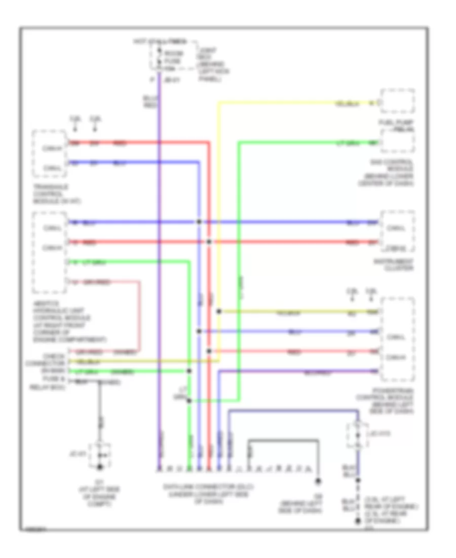
COMPUTER DATA LINES
Computer Data Lines Wiring Diagram for Mazda 6 i 2004
List of elements for Computer Data Lines Wiring Diagram for Mazda 6 i 2004:

AIR CONDITIONINGCOOLING FANANTI-THEFTCOMPUTER DATA LINESDEFOGGERSANTI-LOCK BRAKESGROUND DISTRIBUTIONCRUISE CONTROLENGINE PERFORMANCEEXTERIOR LIGHTSHORNINSTRUMENT CLUSTERINTERIOR LIGHTSPOWER SEATSPOWER DISTRIBUTIONHEADLIGHTSPOWER DOOR LOCKSPOWER WINDOWSPOWER MIRRORSPOWER TOP/SUNROOFRADIOSTARTING/CHARGINGSUPPLEMENTAL RESTRAINTSTRUNK, TAILGATE, FUEL DOORTRANSMISSIONWARNING SYSTEMSWIPER/WASHER