SUPPLEMENTAL RESTRAINTS
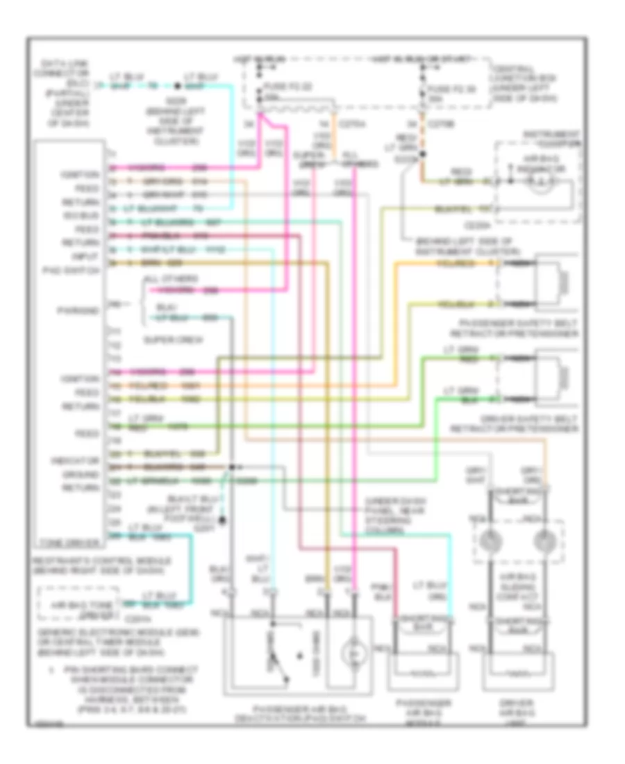
Supplemental Restraint Wiring Diagram for Ford Pickup F250 Super Duty 2002
 https://portal-diagnostov.com/license.html
Automotive Electricians Portal FZCO
Automotive Electricians Portal FZCO
https://portal-diagnostov.com/license.html
https://portal-diagnostov.com/license.html
Automotive Electricians Portal FZCO
Automotive Electricians Portal FZCO
List of elements for Supplemental Restraint Wiring Diagram for Ford Pickup F250 Super Duty 2002:
- (behind left side of instrument cluster)
- (in left front footwell) g201
- (partial) (under center of dash)
- (under dash panel, near steering column)
- 1000 ohms
- 500 ohms
- Air bag indicator
- Air bag sliding contact
- Air bag tone driver
- All others
- C201a
- C220a
- C270a
- C270b
- Central junction box (under left side of dash)
- Data link connector (dlc)
- Driver air bag unit
- Driver safety belt retractor pretensioner
- Feed
- Fuse f2.22 10a
- Fuse f2.30 30a
- Generic electronic module (gem) or central timer module (behind left side of dash)
- Ground
- Hot in run
- Hot in run or start
- Ignition
- Indicator
- Input
- Instrument cluster
- Iso bus
- Nca
- Pad switch
- Passenger air bag deactivation (pad) switch
- Passenger air bag module
- Passenger safety belt retractor pretensioner
- Pin shorting bars connect when module connector is disconnected from harness, between (pins 3-4, 6-7, 8-9 & 20-21)
- Pwr/gnd
- Restraints control module (behind right side of dash)
- Return
- S208
- S229 (behind left side of instrument cluster)
- S237
- Shorting bar
- Super crew
- Tone driver
 Čeština
 Dansk
Dansk Deutsch
 Ελληνικά
 English
 English
 Español
 Suomi
Suomi Français
 Français
 עברית
עברית Hrvatski
 Magyar
 Italiano
 日本語
日本語 Nederlands
 Polski
 Português
 Português
 Română
 Русский
 Slovenčina
 Slovenščina
 Svenska
 Türkçe
 中文 (中国)
 한국어
한국어
