Čeština
 Dansk
Dansk Deutsch
 Ελληνικά
 English
 English
 Español
 Suomi
Suomi Français
 Français
 עברית
עברית Hrvatski
 Magyar
 Italiano
 日本語
日本語 Nederlands
 Polski
 Português
 Português
 Română
 Русский
 Slovenčina
 Slovenščina
 Svenska
 Türkçe
 中文 (中国)

RADIO
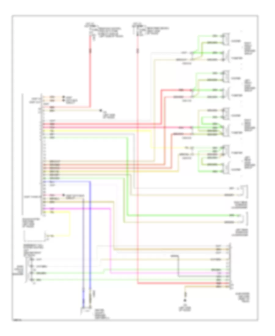
COMAND Actuation Wiring Diagram (1 of 2) for Mercedes-Benz CLS550 2011


List of elements for COMAND Actuation Wiring Diagram (1 of 2) for Mercedes-Benz CLS550 2011:
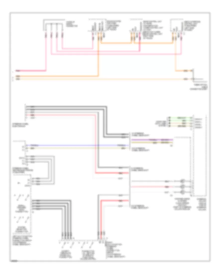
COMAND Actuation Wiring Diagram (2 of 2) for Mercedes-Benz CLS550 2011
List of elements for COMAND Actuation Wiring Diagram (2 of 2) for Mercedes-Benz CLS550 2011:
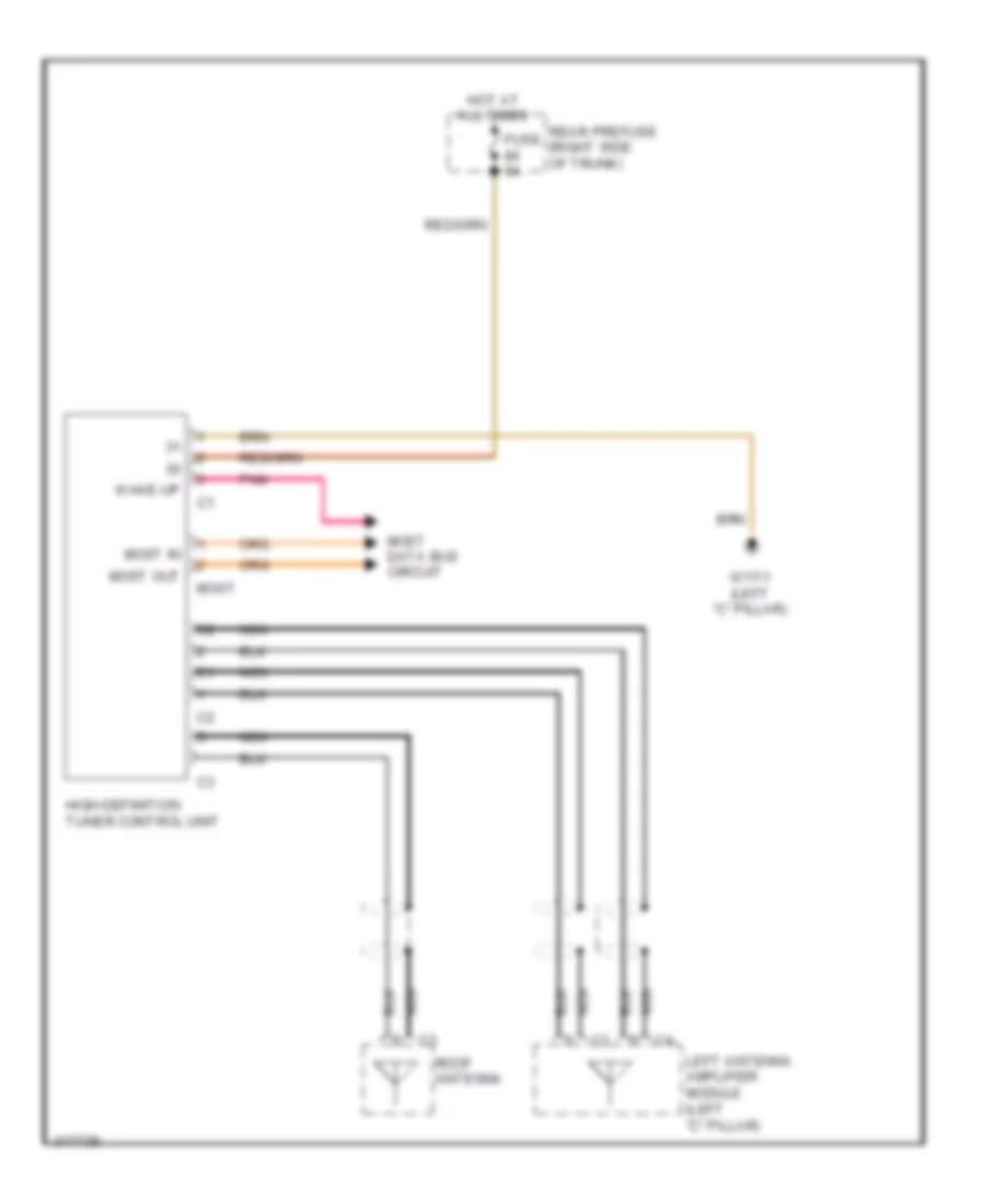
High Definition Tuner Wiring Diagram for Mercedes-Benz CLS550 2011
List of elements for High Definition Tuner Wiring Diagram for Mercedes-Benz CLS550 2011:
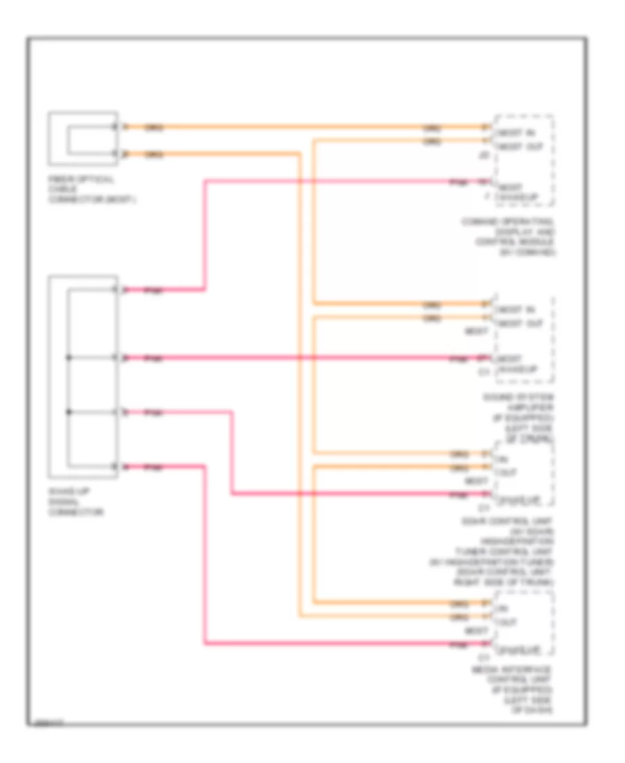
MOST Data Bus Wiring Diagram for Mercedes-Benz CLS550 2011
List of elements for MOST Data Bus Wiring Diagram for Mercedes-Benz CLS550 2011:
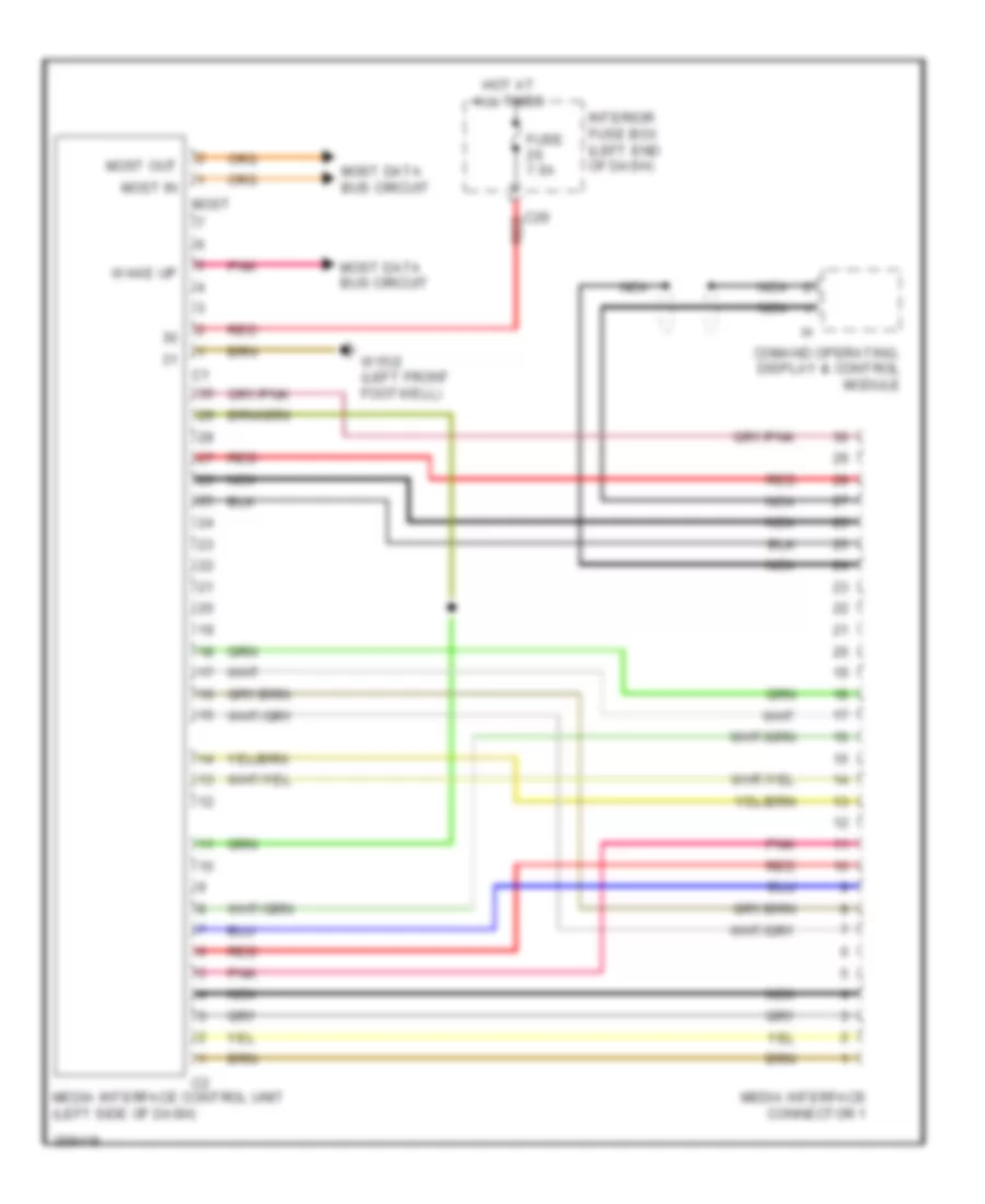
Multimedia Interface Wiring Diagram for Mercedes-Benz CLS550 2011
List of elements for Multimedia Interface Wiring Diagram for Mercedes-Benz CLS550 2011:
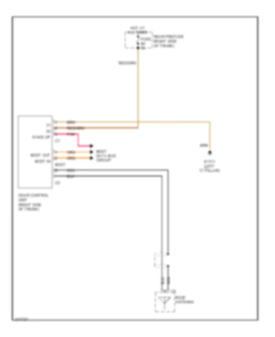
Satellite Radio Wiring Diagram for Mercedes-Benz CLS550 2011
List of elements for Satellite Radio Wiring Diagram for Mercedes-Benz CLS550 2011:
Sound Amplifier Wiring Diagram for Mercedes-Benz CLS550 2011
List of elements for Sound Amplifier Wiring Diagram for Mercedes-Benz CLS550 2011: