CRUISE CONTROL
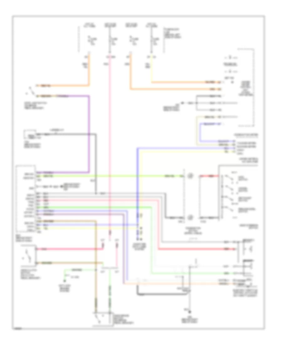
Cruise Control Wiring Diagram for Nissan Maxima SL 2004
List of elements for Cruise Control Wiring Diagram for Nissan Maxima SL 2004:
- (behind right end of dash) m80
- (or pnk)
- 1q e30
- 4 speed a/t
- A/t
- Anti-lock brakes system
- Ascd brake switch (on brake pedal bracket)
- Ascd clutch switch (on clutch pedal bracket)
- Ascd steering switch
- Ascd sw
- Avcc2
- Bnc sw
- Brk sw
- Can-h
- Can-l
- Cancel switch
- Close
- Combination meter
- Combination switch (spiral cable)
- Computer data lines system
- Cruise ind
- Ecm (behind right side of dash)
- Electric throttle control actuator (on throttle body)
- F54
- F57
- Fuse 10a
- Fuse block (j/b) (behind left side of dash)
- Gnd
- Gnd-a
- Gnd-a2
- Hot at all times
- Hot in on or start
- M/t
- M102
- M30
- M57 (behind right side of dash)
- M80 (behind right end of dash)
- M82
- Main switch
- Motor 1
- Motor 2
- Nca
- Open
- Pnk
- Red
- Resume/accel switch
- Rx(comb meter)
- Sens gnd
- Sensor 1
- Sensor 2
- Set ind
- Set/coast switch
- Stop lamp switch (on brake pedal bracket)
- Tcm (behind right side of dash)
- Tps1
- Tps2
- Tx(comb meter)
- Unfied meter & a/c amplifier
- Unified meter control unit (w/odo/ trip meter)
- W/ vdc
 Čeština
 Dansk
Dansk Deutsch
 Ελληνικά
 English
 English
 Español
 Suomi
Suomi Français
 Français
 עברית
עברית Hrvatski
 Magyar
 Italiano
 日本語
日本語 한국어
한국어 Nederlands
 Português
 Português
 Română
 Русский
 Slovenčina
 Slovenščina
 Svenska
 Türkçe
 中文 (中国)
 Polski