AUTOMOTIVE ELECTRICIANS PORTAL

WARNING SYSTEMS – Ford Pickup F150 2011 – SYSTEM WIRING DIAGRAMS

WARNING SYSTEMS

Chime Wiring Diagram for Ford Pickup F150 2011

Chime Wiring Diagram for Ford Pickup F150 2011 https://portal-diagnostov.com/license.html
https://portal-diagnostov.com/license.html Automotive Electricians Portal FZCO Automotive Electricians Portal FZCO
Download PDF file

List of elements for Chime Wiring Diagram for Ford Pickup F150 2011:

  • (not used)
  • Auto
  • Auto lp on
  • Body control module (bcm) (right kick panel)
  • Brake fluid level switch (brake fluid reservoir)
  • Brk fluid sw
  • Brk fluid sw rtn
  • C215
  • C219
  • C2280a
  • C2280b
  • C2280c
  • C2280f
  • C237
  • C2414a
  • C310a
  • C310b
  • C311
  • C316
  • C327
  • Cbp31
  • Cdc30
  • Clf19
  • Clf23
  • Clf24
  • Cls34
  • Cmc19
  • Cmc25
  • Computer data lines system
  • Cpl26
  • Cpl31
  • Cpl36
  • Cpl39
  • Cr201
  • Driv buckle sw
  • Driver safety belt buckle switch (seat belt buckle assembly)
  • Fuse 10a
  • Fuse 15a
  • G102 (left front of engine compt)
  • G200 (left kick panel)
  • G200 (super cab) (left kick panel) g201 (regular cab) (right kick panel)
  • G201 (right kick panel)
  • G202 (left side of dash)
  • G300 (under center console)
  • Hdlp off
  • Hdlp on
  • Head
  • Headlamp switch
  • Hot at all times
  • Hot in start or run
  • Hs can +
  • Hs can -
  • Hs can+
  • Hs can-
  • If equipped
  • Ignition switch
  • Instrument panel cluster (ipc)
  • Key in ign
  • Key in ignition
  • Left front door latch (rear of driver's door)
  • Left rear door ajar switch (left rear door)
  • Left rear door latch
  • Lf door ajar
  • Lr door ajar
  • Micro
  • Ms can +
  • Ms can -
  • Multi- function switch
  • Nca
  • Off
  • Park
  • Park brk
  • Parking brake switch (parking brake assembly)
  • Prk lp on
  • Restraints control module (rcm) (under center console)
  • Rf door ajar
  • Right front door latch (rear of front passenger's door)
  • Right rear door ajar switch (right rear door)
  • Right rear door latch
  • Rmc19
  • Rr door ajar
  • Run/start
  • S242
  • S353
  • S500
  • S600
  • S700 (if equipped)
  • S800 (if equipped)
  • Steering column control module (steering column)
  • Super cab & regular cab
  • Super crew w/ power equipment
  • Vdb04
  • Vdb05
  • Vdb06
  • Vdb07
  • W/ power equipment
  • W/o power equipment

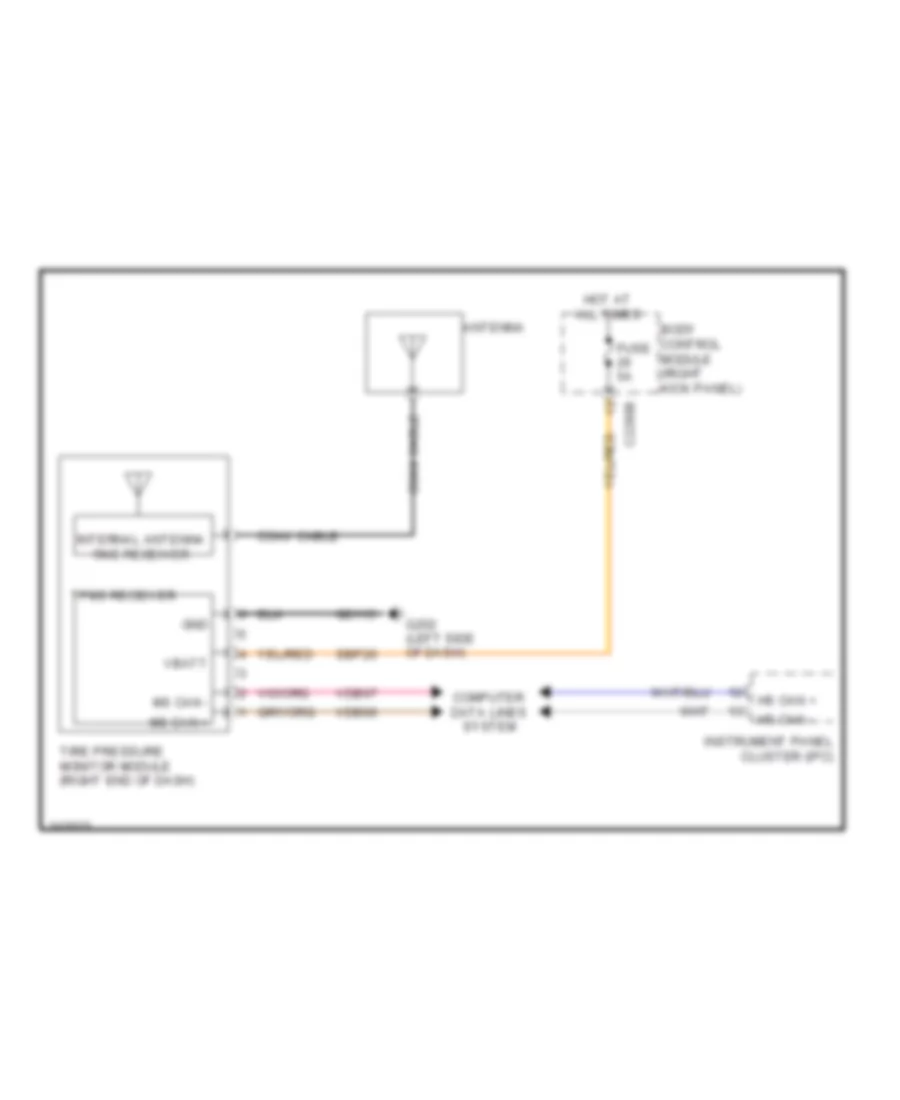
Tire Pressure Monitoring Wiring Diagram for Ford Pickup F150 2011

Tire Pressure Monitoring Wiring Diagram for Ford Pickup F150 2011 https://portal-diagnostov.com/license.html
https://portal-diagnostov.com/license.html Automotive Electricians Portal FZCO Automotive Electricians Portal FZCO
Obtenha acesso a todos os diagramas de fiação do carroDownload PDF file

List of elements for Tire Pressure Monitoring Wiring Diagram for Ford Pickup F150 2011:

  • Antenna
  • Body control module (right kick panel)
  • C2280b
  • Coax cable
  • Computer data lines system
  • Fuse 5a
  • G202 (left side of dash)
  • Gd113
  • Gnd
  • Hot at all times
  • Hs can +
  • Hs can -
  • Instrument panel cluster (ipc)
  • Internal antenna rke receiver
  • Ms can +
  • Ms can -
  • Sbp26
  • Tire pressure monitor module (right end of dash)
  • Tpms receiver
  • Vbatt
  • Vdb06
  • Vdb07