TRANSMISSION
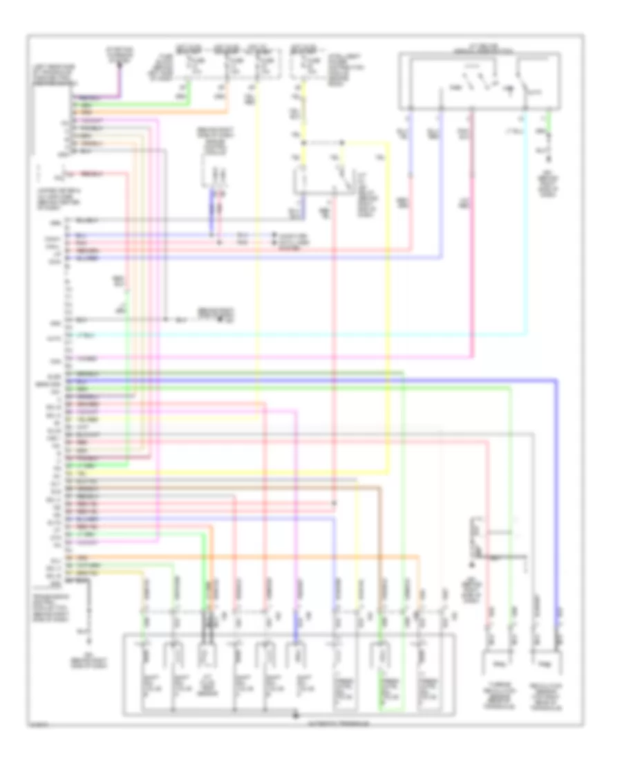
A/T Wiring Diagram for Nissan Maxima SL 2005
List of elements for A/T Wiring Diagram for Nissan Maxima SL 2005:
- (behind right side of dash) engine control module
- (behind right side of dash) m61
- (left rear side of transaxle) park/neutral position switch
- A/t device (manual mode switch)
- A/t fluid temp sensor
- A/t pv ign relay (behind right end of dash)
- Auto
- Automatic transaxle
- Can-h
- Can-l
- Cntrl sol valve a
- Cntrl sol valve b
- Cntrl sol valve c
- Computer data lines system
- Dwn
- F30
- F62
- Fuse 10a
- Fuse block (behind left side of dash)
- Gnd
- Hot at all times
- Hot in on or start
- Ig1
- Ig2
- Igr5
- Intelligent power distribution module (engine room)
- M61 (behind right side of dash)
- Man
- Nc+
- Nc-
- Nca
- Otg
- Pnk
- Press
- Red
- Revolution sensor (top right rear of transaxle)
- Sens gnd
- Shift sol valve a
- Shift sol valve b
- Shift sol valve c
- Shift sol valve d
- Shift sol valve e
- Sls
- Slsg
- Slt
- Sltg
- Slu
- Slug
- Sol a
- Sol b
- Sol c
- Sol d
- Sol e
- Starting/ charging system
- Transmission control module (tcm) (behind right side of dash)
- Turbine revolution sensor (rear of transaxle)
- Unified meter & a/c amplifier (behind center of dash)
- Vss 1
 Čeština
 Dansk
Dansk Deutsch
 Ελληνικά
 English
 English
 Español
 Suomi
Suomi Français
 Français
 עברית
עברית Hrvatski
 Magyar
 Italiano
 日本語
日本語 한국어
한국어 Nederlands
 Polski
 Português
 Português
 Русский
 Slovenčina
 Slovenščina
 Svenska
 Türkçe
 中文 (中国)
 Română