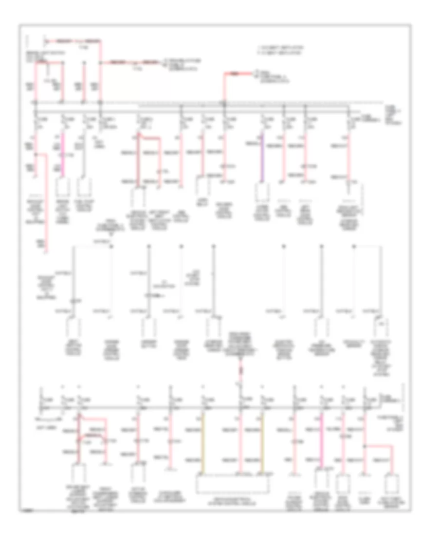
БЛОК ПРЕДОХРАНИТЕЛЕЙ И РЕЛЕ
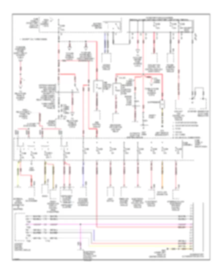
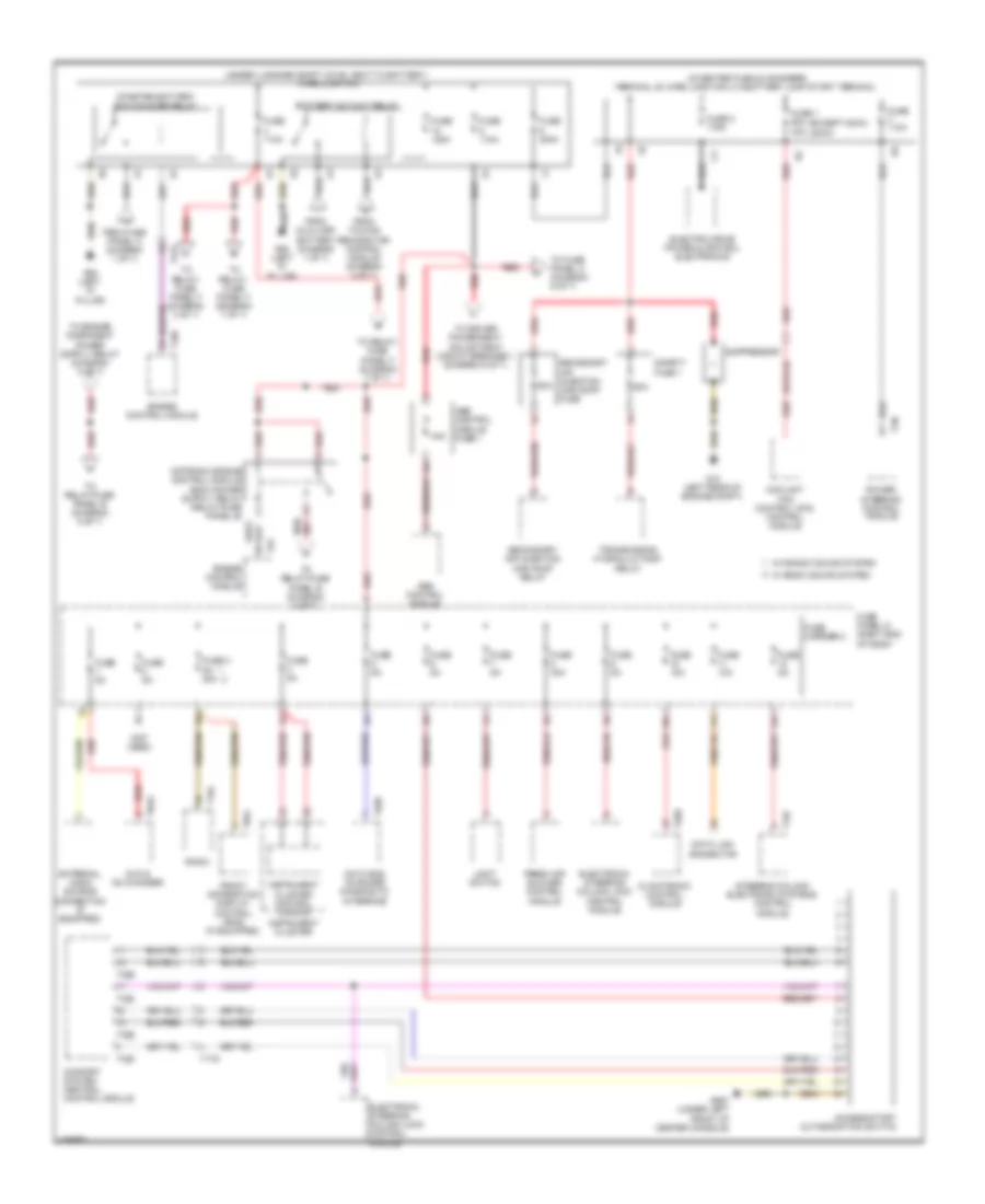
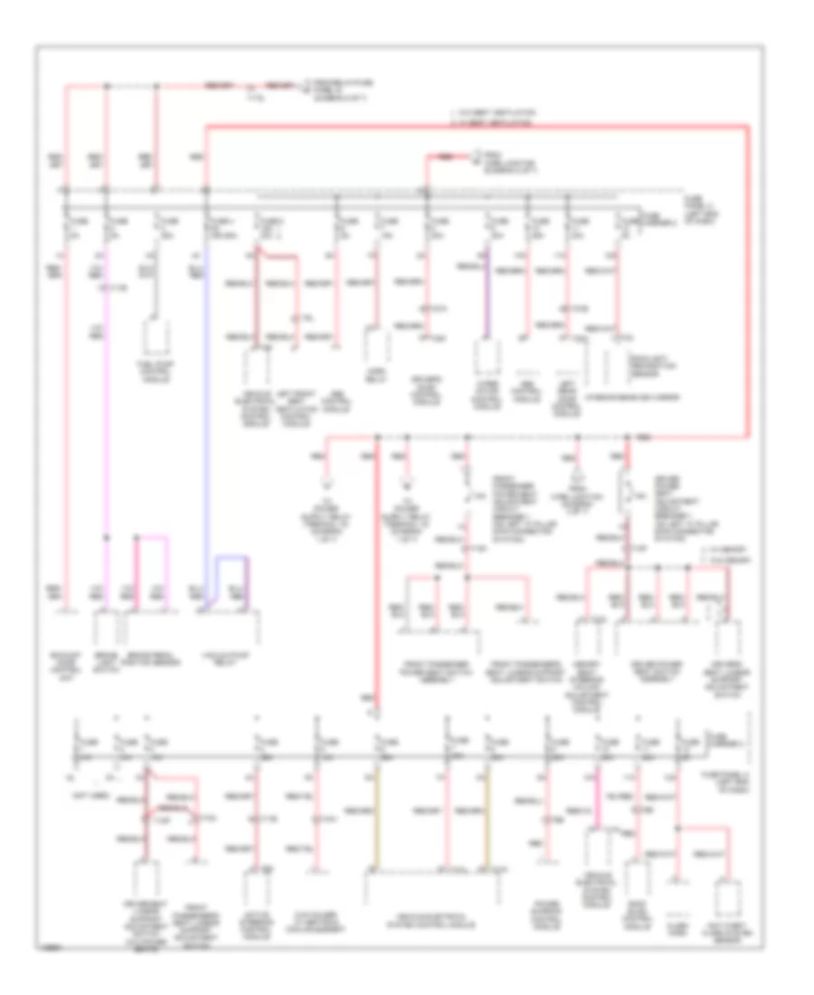
Электросхема блока предохранителей и реле, кроме гибрида (1 из 8) для Audi Q5 Prestige 2014

Электросхема блока предохранителей и реле, кроме гибрида (1 из 8) для Audi Q5 Prestige 2014 - Список элементов:
- (not used)
- 10a
- 11a
- 12a
- 2.0l turbo
- 3.0l sc & 3.0l turbo diesel
- All wheel drive control module
- Battery
- Battery monitoring control module (left side of luggage compt)
- Data bus on board diagnostic interface
- Digital sound system control module
- Electro- mechanical parking brake control module
- Electronic damping control module
- From battery monitoring control module (diagram 1 of 8)
- From fuse panel c (diagram 8 of 8)
- Front passenger's door control module
- Fuse 10a
- Fuse 110a
- Fuse 15a
- Fuse 20a
- Fuse 25a
- Fuse 30a
- Fuse 3a
- Fuse 40a
- Fuse 5a
- Fuse carrier
- Fuse carrier 1
- Fuse n/a
- Fuse panel a (on battery positive terminal)
- G51 (right "d" pillar)
- G624 (in luggage compartment near starter battery)
- Generator & voltage regulator
- Radio
- Rear lid control module
- Rear window defogger relay
- Red
- Relay/fuse panel f (right side of luggage compt)
- Right rear door control module
- Seat heating control module
- T10ag
- T12d
- T17e
- T17q
- T17r
- T20d
- T20g
- T20i
- T20m
- T27d
- T32h
- T5l
- Telephone baseplate (w/ center armrest)
- To fuse 2 (diagram 2 of 8)
- To relay/ fuse panel b (diagram 5 of 8)
- To relay/ fuse panel f (diagram 7 of 8)
- To sockets relay (diagram 4 of 8)
- To voltage stabilizer (diagram 1 of 8)
- Towing recognition control module
- Voltage stabilizer (w/ stop/ start system) (right side of luggage compt)
- W/ stop/ start system
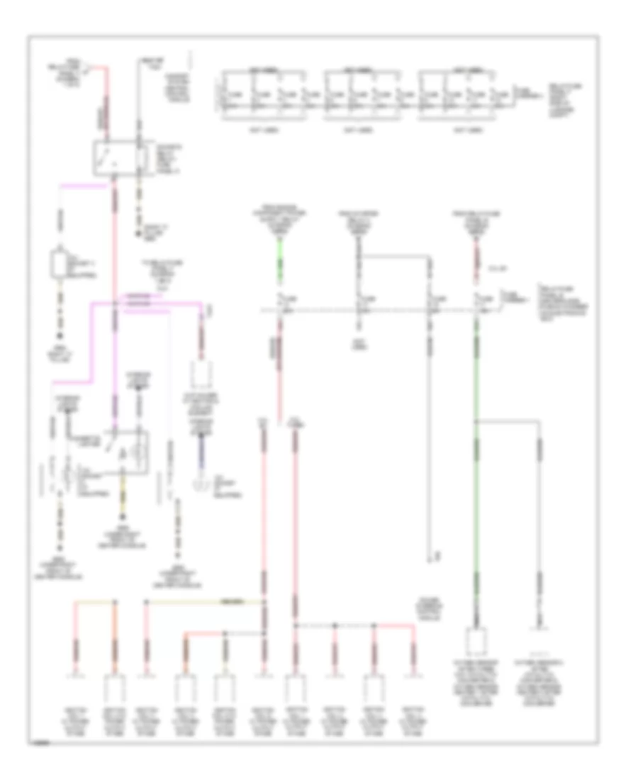
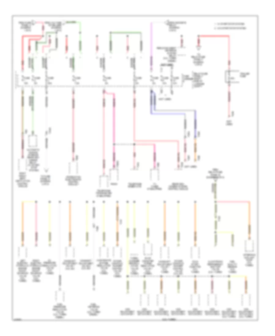
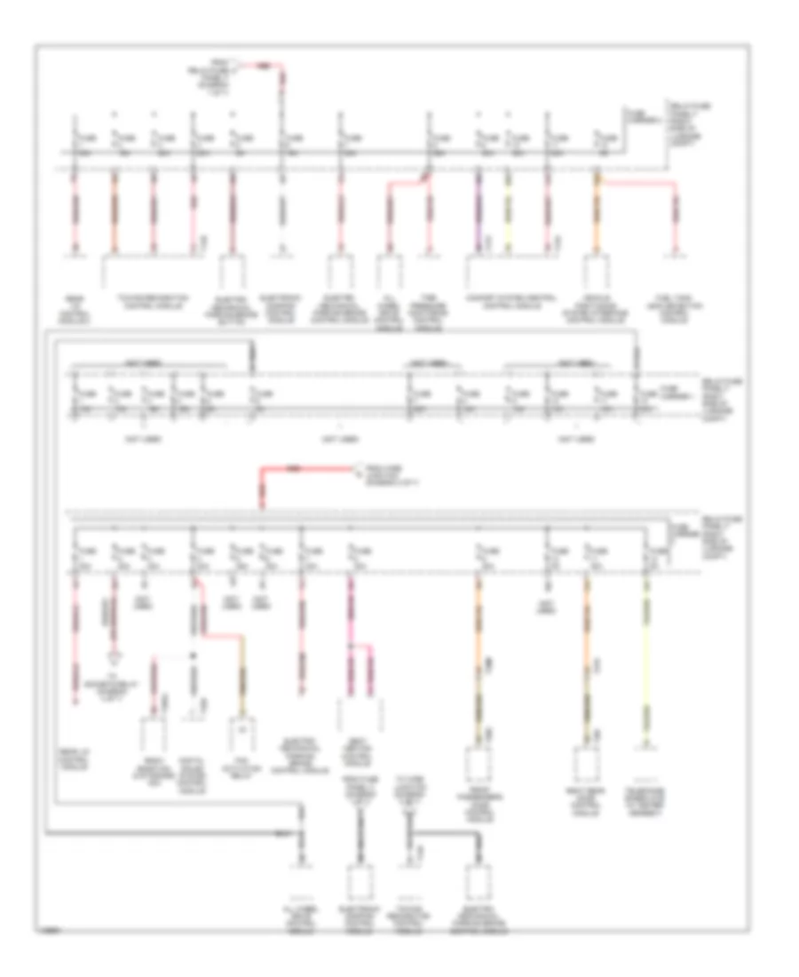
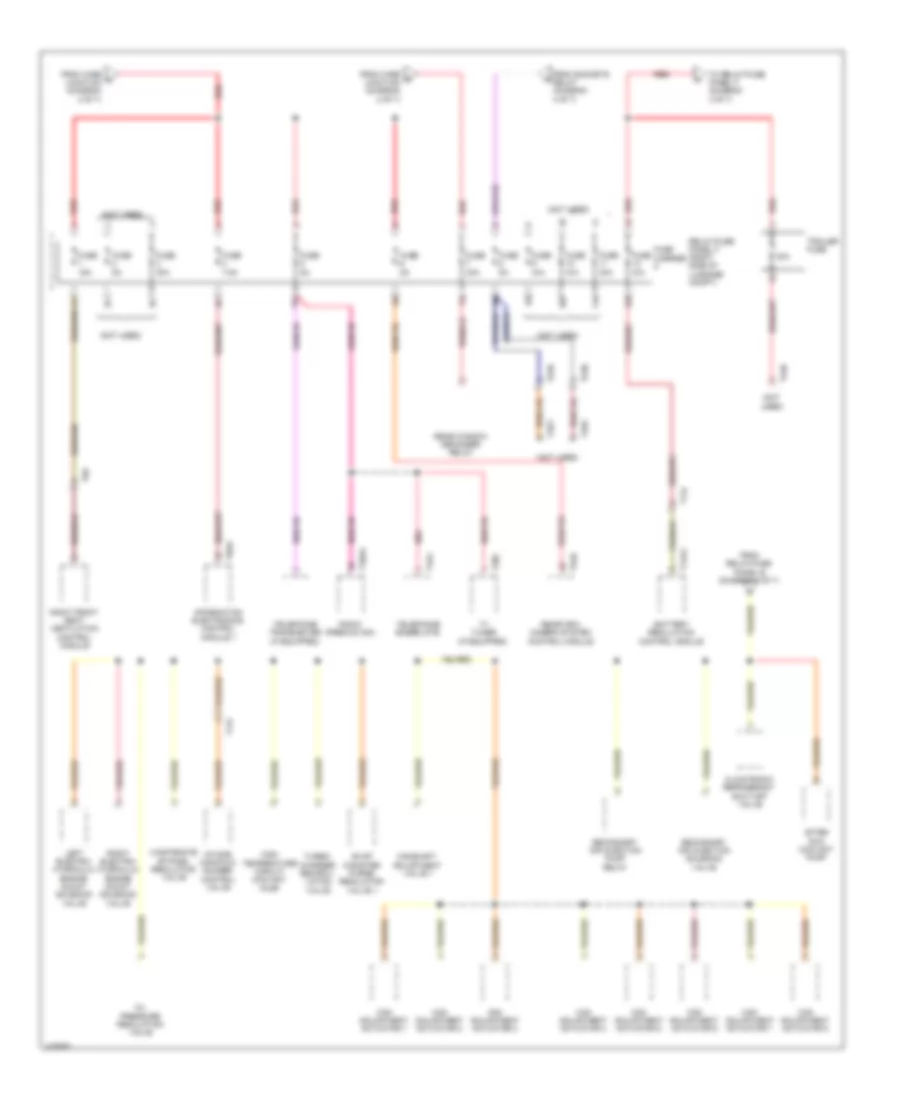
Электросхема блока предохранителей и реле, кроме гибрида (2 из 8) для Audi Q5 Prestige 2014
Электросхема блока предохранителей и реле, кроме гибрида (2 из 8) для Audi Q5 Prestige 2014 - Список элементов:
- (except 400w) (400w)
- (in center plenum chamber) terminal 30 wire junction 2 w/battery jump start terminal
- (not used)
- 10a
- 11a
- 12a
- 2.0l turbo
- 3.0l sc
- 3.0l sc & 3.0l turbo diesel
- 3.0l turbo diesel
- 3.0l turbo diesel 2.0l turbo
- 40a
- 40a b2
- 50a
- 80a
- Abs control module
- Abs control module fuse 1
- Access/start authorization switch
- Air bag control module
- Automatic glow-time control module
- Battery interrupt igniter
- Climatronic control module
- Comfort system central control module
- Coolant fan control (fc) control module
- Coolant fan control (fc) control module 2 (800w/1000w)
- Data bus on board diagnostic interface
- Data link connector
- Dvd & cd changer
- Electronic steering column lock control module
- Engine control module
- Engine glow plug fuse strip
- Except 3.0l turbo diesel
- External audio source connection (if equipped)
- Fresh air blower control module
- From a fuse 1 (diagram 1 of 8)
- From relay/fuse panel f (diagram 7 of 8)
- Front information display control head (if equipped)
- Fuse 10a
- Fuse 110a
- Fuse 3 5a 20a
- Fuse 40a
- Fuse 5a
- Fuse 60a
- Fuse carrier 2
- Fuse panel a (on battery positive terminal)
- Fuse panel d (right end of dash)
- G12 (left rear of engine compt)
- G687 (under left front of center console)
- Generator & voltage regulator
- Instrument cluster
- Instrument cluster control module
- Light switch
- Power steering control module
- Radio
- Red
- Safety fuse 1
- Secondary air injection (air) pump fuse
- Secondary air injection (air) pump relay
- Starter
- Steering column electronic systems control module
- Suppressor
- T16f
- T16l
- T17g
- T20d
- T20e
- T2n
- T32c
- T32d
- T8aa
- T8ai
- T91
- T94
- To auxiliary heater fuse (diagram 3 of 8)
- To driver power seat adjustment circuit breaker 1 (diagram 8 of 8)
- To fuse panel c (diagram 6 of 8)
- To relay/fuse panel b (diagram 5 of 8)
- W/ mmi
- W/ start/ stop system
- W/ start/stop system
- W/o mmi
- W/o start/stop system
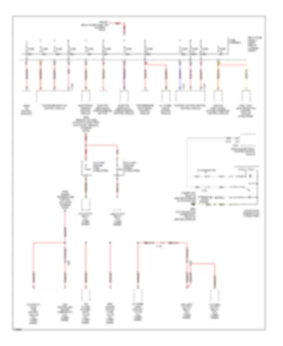
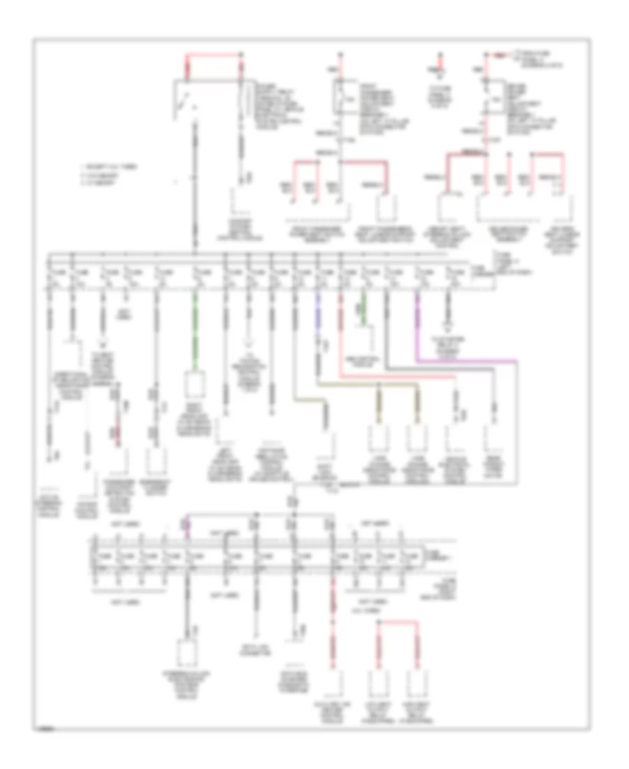
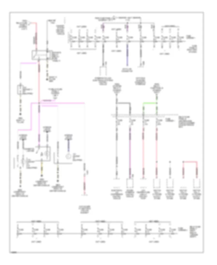
Электросхема блока предохранителей и реле, кроме гибрида (3 из 8) для Audi Q5 Prestige 2014
Электросхема блока предохранителей и реле, кроме гибрида (3 из 8) для Audi Q5 Prestige 2014 - Список элементов:
- (under left front of center console) (w/ navigation) g687
- 10a
- 11a
- 12a
- 40a
- 60a
- Air filter bypass door valve (3.0l turbo) diesel
- All wheel drive control module
- Automatic glow time control module (3.0l turbo) diesel
- Auxiliary heater fuse (if equipped)
- Auxiliary heater fuse 2 (if equipped)
- Comfort system central control module
- Cylinder head coolant valve (3.0l turbo) diesel
- Egr cooler switch over valve (3.0l turbo) diesel
- Electro- mechanical parking brake button
- Electro- mechanical parking brake control module
- Electronic damping control module
- From engine temperature control actuator (diagram 5 of 8)
- From relay/fuse panel f (diagram 7 of 8)
- From terminal 30 wire junction 2 w/battery jump start terminal (diagram 2 of 8)
- Fuel tank leak detection control module (if equipped)
- Fuse 15a
- Fuse 20a
- Fuse 30a
- Fuse 35a
- Fuse 5a
- Fuse carrier 2
- G688 (w/o navigation) (under right front of center console)
- High heat output relay (3.0l turbo) diesel
- High output relay (3.0l turbo diesel)
- Interior lights system
- Low heat output relay (3.0l turbo) diesel
- Low output relay (3.0l turbo diesel)
- Map controlled engine thermostat (3.0l turbo) diesel
- Rear lid control module 2
- Red
- Relay/fuse panel f (right side of luggage compt)
- Start/stop mode button (if equipped)
- T10d
- T12d
- T17b
- T17c
- T17o
- T17p
- T17q
- T32a
- Tire pressure monitoring control module
- Towing recognition control module
- Vehicle electrical system control module
- Vehicle positioning system interface control module
- W/o navigation
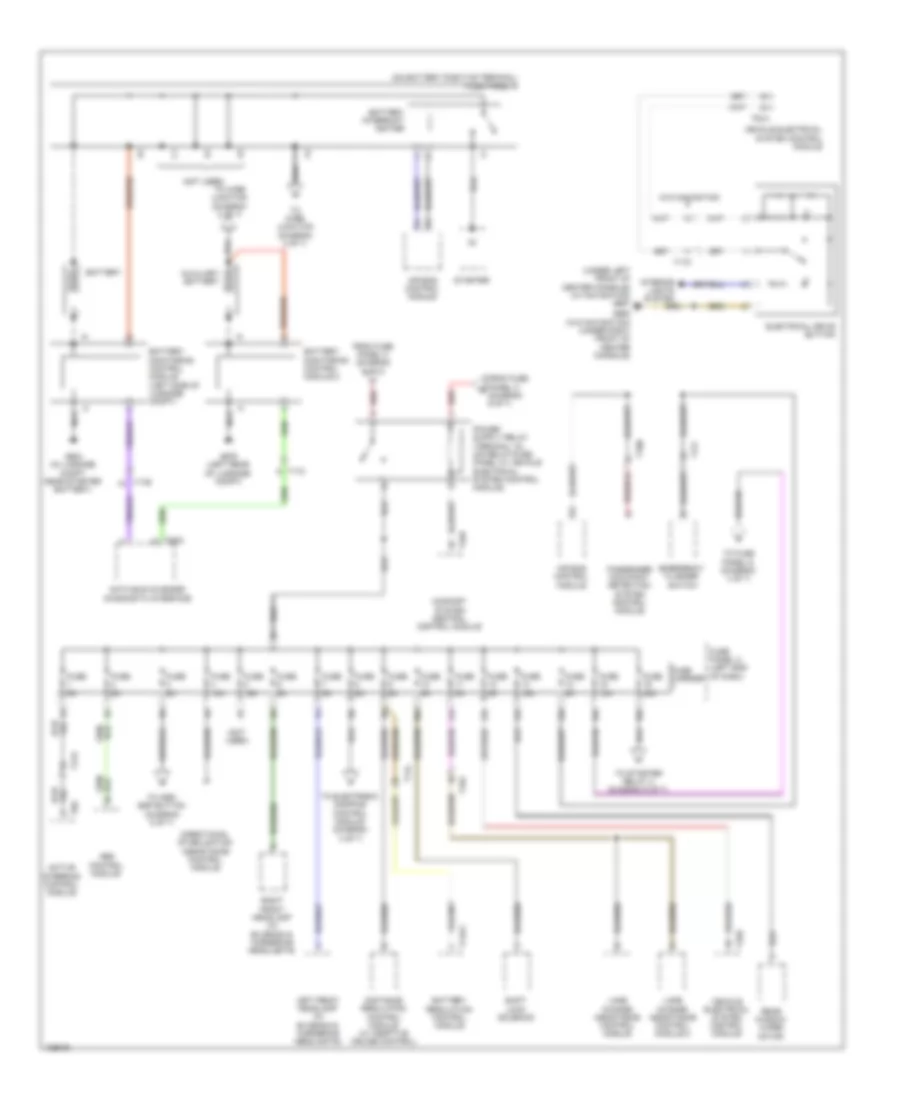
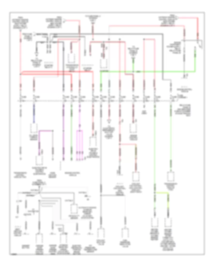
Электросхема блока предохранителей и реле, кроме гибрида (4 из 8) для Audi Q5 Prestige 2014
Электросхема блока предохранителей и реле, кроме гибрида (4 из 8) для Audi Q5 Prestige 2014 - Список элементов:
- (not used)
- (right "c" pillar) g663
- 12v socket (if equipped)
- 12v socket 3 (if equipped)
- 13a
- 14a
- 15a
- 17a
- 2.0l turbo
- 3.0l sc
- Cigarette lighter
- Comfort system central control module
- Cup holder w/ heating & cooling element
- From relay/fuse panel b (diagram 5 of 8)
- From relay/fuse w panel f (diagram 1 of 8)
- From starter relay 2 (diagram 5 of 8)
- Fuse 15a
- Fuse 20a
- Fuse 5a
- Fuse carrier 1
- Fuse carrier 4
- Fuse n/a
- G663 (right "c" pillar)
- G688 (under right front of center console)
- Ignition coil 1 w/ power output stage
- Ignition coil 2 w/ power output stage
- Ignition coil 3 w/ power output stage
- Ignition coil 4 w/ power output stage
- Ignition coil 5 w/ power output stage
- Ignition coil 6 w/ power output stage
- Interior lights system
- Nca
- Oxygen sensor 2 after catalytic converter & oxygen sensor heater 2 after catalytic converter
- Oxygen sensor after three way catalytic converter & oxygen sensor heater 1 after catalytic converter
- Power steering control module
- Relay/fuse panel b (driver's side plenum chamber on electronics box)
- Relay/fuse panel f (right side of luggage compt)
- Sockets relay (relay/ fuse panel f)
- T32c
- T4av
- T6h
- To relay/fuse panel f (diagram 7 of 8)
Электросхема блока предохранителей и реле, кроме гибрида (5 из 8) для Audi Q5 Prestige 2014
Электросхема блока предохранителей и реле, кроме гибрида (5 из 8) для Audi Q5 Prestige 2014 - Список элементов:
- 10a
- 11a
- 12a
- 16a
- 2.0l turbo
- 3.0l sc
- 3.0l turbo diesel
- Auxiliary engine coolant pump relay (3.0l sc)
- Charge air cooling pump (3.0l sc)
- Coolant fan control (fc) control module
- Coolant fan control (fc) control module 2 (800w/1000w)
- Crankcase ventilation shut-off valve (3.0l sc)
- Engine control module
- Engine control module (ecm)
- Engine temperature control actuator (3.0l sc)
- Evap canister purge regulator valve 1 (3.0l sc)
- Except 3.0l turbo diesel
- From fuse h panel c (diagram 8 of 8)
- From terminal 30 wire junction 2 w/ battery jump start terminal (diagram 2 of 8)
- From voltage stabilizer (diagram 1 of 8)
- Fuel metering valve
- Fuel pressure regulator valve
- Fuse 10 10a 15a
- Fuse 15a
- Fuse 5 5a 10a
- Fuse 5a
- Fuse 7 10a 15a
- Fuse carrier 1
- Heated oxygen sensor & oxygen sensor heater
- Left electrohydraulic engine mount solenoid valve
- Mass air flow sensor
- Nca
- Nox sensor & nox sensor control module
- Nox sensor 2 & nox sensor control module 2 (w/ reducing agent metering system)
- Oil level thermal sensor
- Oil pressure regulation valve
- Oxygen sensor heater 1 after three way catalytic converter & oxygen sensor after three way catalytic converter (2.0l turbo) heated oxygen sensor 2 & oxygen sensor heater 2 (3.0l sc)
- Red
- Reducing agent metering system control module (if equipped)
- Relay/fuse panel b (driver's side plenum chamber on electronics box)
- Right electrohydraulic engine mount solenoid valve
- Secondary air injection (air) pump relay (3.0l sc)
- Secondary air injection (air) solenoid valve (3.0l sc)
- Starter
- Starter relay
- Starter relay 2
- T14e
- T17q
- T17r
- T5l
- T91
- T94
- To climatronic refrigerant shut-off valve (diagram 7 of 8)
- To fuse panel c (diagram 6 of 8)
- To map controlled engine thermostat (diagram 3 of 8)
- To relay/fuse panel b (diagram 4 of 8)
- Transmission control module (tcm)
- W/ start/stop system
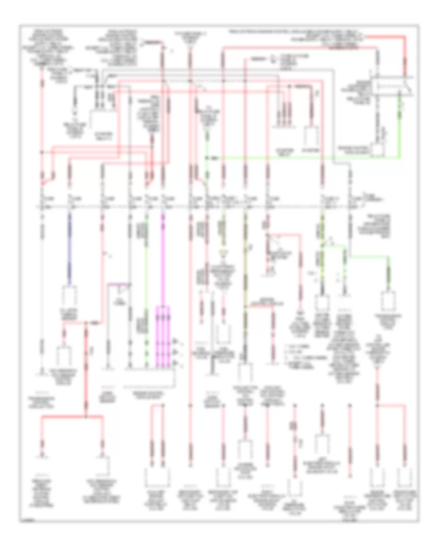
Электросхема блока предохранителей и реле, кроме гибрида (6 из 8) для Audi Q5 Prestige 2014
Электросхема блока предохранителей и реле, кроме гибрида (6 из 8) для Audi Q5 Prestige 2014 - Список элементов:
- (not used)
- 10a
- 11a
- 12a
- 3.0l sc
- A/c pressure/ temperature sensor
- Abs control module
- Active steering control module
- Air quality sensor
- Alarm horn
- Anti-theft alarm system sensor
- Asr/esp button
- Automatic dimming interior rearview mirror relay (w/ start/ stop system)
- Brake light switch (3.0l sc & 2.0l turbo)
- Brake light switch (3.0l turbo diesel)
- Cupholder w/ heating & cooling element
- Driver seat lumbar support adjustment switch (w/o power seats)
- Driver's door control module
- Electro- mechanical parking brake button
- Exhaust door control unit (if equipped)
- Exhaust door control unit 2 (if equipped)
- From front passenger power seat adjustment circuit breaker 1 (diagram 8 of 8)
- From fuse panel a (diagram 2 of 8)
- From fuse panel c (diagram 8 of 8)
- From relay/fuse panel b (diagram 5 of 8)
- Front passenger's seat lumbar support adjustment switch
- Fuel pump control module
- Fuse 10a
- Fuse 15a
- Fuse 20a
- Fuse 25a
- Fuse 30a
- Fuse 35a
- Fuse 4 5a (or 25a)
- Fuse 5 15a 30a
- Fuse 5a
- Fuse carrier 2
- Fuse carrier 3
- Fuse n/a
- Fuse panel c (left end of dash)
- Garage door opener control head
- Garage door opener control module
- Horn relay
- Interior rearview mirror
- Left front seat ventilation control module
- Left rear door control module
- Power sunroof control module
- Rain/light recognition sensor
- Red
- Roof blind control module
- Seat heating control module
- T10m
- T10p
- T17b
- T17e
- T17l
- T17m
- T17n
- T17q
- T20f
- T20h
- T27a
- T27b
- T3c
- T4av
- T5d
- T6e
- T6f
- T6l
- T8c
- T8f
- Vehicle electrical system control module
- W/ navigation
- W/ seat ventilation
- W/o seat ventilation
- W/o start/ stop system
- Wiper motor control module
Электросхема блока предохранителей и реле, кроме гибрида (7 из 8) для Audi Q5 Prestige 2014
Электросхема блока предохранителей и реле, кроме гибрида (7 из 8) для Audi Q5 Prestige 2014 - Список элементов:
- (2.0l turbo)
- (not used)
- 10a
- 30a
- After-run coolant pump (2.0l turbo)
- Automatic dimming interior rearview mirror relay (w/ start/ stop system)
- Cam adjustment actuator 1
- Cam adjustment actuator 2
- Cam adjustment actuator 3
- Cam adjustment actuator 4
- Cam adjustment actuator 5
- Cam adjustment actuator 6
- Cam adjustment actuator 7 (2.0l turbo)
- Cam adjustment actuator 8 (2.0l turbo)
- Camshaft adjustment valve 1 (2.0l turbo)
- Camshaft adjustment valve 1 (3.0l sc)
- Camshaft adjustment valve 2 (3.0l sc)
- Climatronic refrigerant shut-off valve (2.0l turbo)
- Cold start injector (2.0l turbo)
- Evap canister purge regulator valve 1 (2.0l turbo)
- From fuse x panel a (diagram 1 of 8)
- From relay/fuse panel b (diagram 5 of 8)
- From sockets relay (diagram 4 of 8)
- From voltage f stabilizer (diagram 1 of 8)
- Fuel metering valve (3.0l turbo diesel)
- Fuel pressure regulation valve (3.0l turbo diesel)
- Fuel quality sensor (2.0l turbo)
- Fuse 15a
- Fuse 30a
- Fuse 5a
- Fuse 7.5a
- Fuse carrier
- Fuse n/a
- Information electronics control module 1
- Intake manifold runner control valve (2.0l turbo)
- Intake manifold runner control valve (3.0l sc)
- Left electro- hydraulic engine mount solenoid valve (2.0l turbo)
- Oil pressure regulation valve (2.0l turbo)
- Radio
- Rearview camera system control module
- Red
- Reducing agent metering system relay (3.0l turbo diesel)
- Relay/fuse panel f (right side of luggage compt)
- Right electro- hydraulic engine mount solenoid valve (2.0l turbo)
- Right front seat ventilation control module
- T10ag
- T10d
- T14f
- T17q
- T17w
- T20c
- T2da
- T2db
- T2dy
- T2dz
- T4aj
- T4aq
- T54b
- T6k
- T8ao
- Telephone baseplate
- Telephone transceiver (if equipped)
- To fuse panel d (diagram 2 of 8)
- To relay/fuse panel f (diagram 3 of 8)
- Trailer fuse
- Turbo- charger recircu- lation valve (2.0l turbo)
- Tv tuner (if equipped)
- W/ start/stop system
- W/o start/stop system
- Wastegate bypass regulator valve (2.0l turbo)
Электросхема блока предохранителей и реле, кроме гибрида (8 из 8) для Audi Q5 Prestige 2014
Электросхема блока предохранителей и реле, кроме гибрида (8 из 8) для Audi Q5 Prestige 2014 - Список элементов:
- (not used)
- 10a
- 11a
- 12a
- 13a
- 14a
- 15a
- 16a
- 2.0l turbo
- Abs control module
- Active steering control module
- Air bag control module
- Auxiliary air heater control module
- Comfort system central control module
- Data bus on board diagnostic interface
- Data link connector
- Directional stabilization assistance control module
- Distance regulation control module (w/ adaptive cruise control)
- Driver power seat adjustment circuit breaker 1 (on left "a" pillar 6-pin connector station)
- Driver power seat switch assembly
- Driver's seat lumbar support adjustment switch
- Emergency flasher switch
- Except 2.0l turbo
- From fuse panel a (diagram 2 of 8)
- Front passenger power seat adjustment circuit breaker 1 (on left "a" pillar 6-pin connector station)
- Front passenger power seat switch assembly
- Front passenger's seat lumbar support adjustment switch
- Fuse 10a
- Fuse 15a
- Fuse 40a
- Fuse 5a
- Fuse carrier
- Fuse carrier 1
- Fuse n/a
- Fuse panel c (left end of dash)
- Fuse panel d (right end of dash)
- High heat output relay (if equipped)
- Lane change assistance control module
- Lane change assistance control module 2
- Left front headlamp (w/ bi-xenon & cornering headlights)
- Low heat output relay (if equipped)
- Memory seat/ steering column adjustment control
- Passenger occupant detection system control module
- Rear window wiper motor
- Red
- Right front headlamp (w/ bi-xenon & cornering headlights)
- Shift lock solenoid
- Steering column electronics systems control module
- T10m
- T10n
- T10p
- T12l
- T16f
- T16v
- T17c
- T17e
- T17f
- T20d
- T32b
- T32d
- T8g
- To fuse panel c (diagram 6 of 8)
- To seat heating control module (diagram 6 of 8)
- To starter relay 2 (diagram 5 of 8)
- To towing recognition control module (diagram 1 of 8)
- Vehicle electrical system control module
- W/ memory
- W/o memory
Электросхема блока предохранителей и реле, гибрид (1 из 7) для Audi Q5 Prestige 2014
Электросхема блока предохранителей и реле, гибрид (1 из 7) для Audi Q5 Prestige 2014 - Список элементов:
- (not used)
- (on battery positive terminal) fuse panel a
- (under left front of center console) (w/ navigation) g687
- 10a
- 11a
- 12a
- 13a
- 14a
- 15a
- 16a
- Abs control module
- Active steering control module
- Air bag control module
- Auxiliary battery
- Battery
- Battery interrupt igniter
- Battery monitoring control module (left side of luggage compt)
- Battery monitoring control module 2
- Battery regulation control module
- Comfort system central control module
- Data bus on board diagnostic interface
- Directional stabilization assistance control module
- Distance regulation control module (w/ adaptive cruise control)
- Electrical drive button
- Emergency flasher switch
- From fuse panel c (diagram 6 of 7)
- Fuse 10a
- Fuse 15a
- Fuse 40a
- Fuse 5a
- Fuse carrier
- Fuse panel c (left end of dash)
- G624 (in luggage compt near starter battery)
- G676 (left rear of luggage compt)
- G688 (w/o navigation) (under right front of center console)
- Interior lights system
- Lane change assistance control module
- Lane change assistance control module 2
- Left front headlamp (w/ bi-xenon & cornering headlights)
- Nca
- Passenger occupant detection system control module
- Rear window wiper motor
- Red
- Right front headlamp (w/ bi-xenon & cornering headlights)
- Shift lock solenoid
- Starter
- T10n
- T14ax
- T14l
- T16v
- T17c
- T17e
- T17f
- T20d
- T32a
- T32b
- T32d
- T8g
- To asr/ esp button (diagram 5 of 7)
- To electronic damping control module (diagram 3 of 7)
- To fuse panel d (diagram 4 of 7)
- To starter relay 2 (diagram 5 of 7)
- To wire junction (diagram 2 of 7)
- Vehicle electrical system control module
- W/o navigation
Электросхема блока предохранителей и реле, гибрид (2 из 7) для Audi Q5 Prestige 2014
Электросхема блока предохранителей и реле, гибрид (2 из 7) для Audi Q5 Prestige 2014 - Список элементов:
- (400w)
- (except 400w)
- (in center plenum chamber) terminal 30 wire junction 2 w/battery jump start terminal
- (not used)
- (under luggage compt cove, next to battery) wire junction
- 10a
- 11a
- 12a
- 40a
- 50a
- Abs control module
- Abs control module fuse 1
- Access/start authorization switch
- Battery cut-out relay
- Climatronic control module
- Comfort system central control module
- Coolant fan control (cfc) control module
- Data bus on board diagnostic interface
- Data link connector
- Dvd & cd changer
- Electric drive power & control electronics
- Electronic steering column lock control module
- Engine control module
- External audio source connection (if equipped)
- Fresh air blower control module
- From auxiliary battery (diagram 1 of 7)
- From fuse panel a (diagram 1 of 7)
- From towing recognition control module (diagram 3 of 7)
- Front information display control head (if equipped)
- Fuse 1 60a 40a
- Fuse 10a
- Fuse 110a
- Fuse 125a
- Fuse 2 175a
- Fuse 200a
- Fuse 3 5a 20a
- Fuse 40a
- Fuse 5a
- Fuse carrier 2
- Fuse panel d (right end of dash)
- G12 (left rear of engine compt)
- G50 (left "d" pillar)
- G687 (under left front of center console)
- Instrument cluster
- Instrument cluster control module
- Light switch
- Power steering control module
- Radio
- Red
- Safety fuse 1
- Secondary air injection (air) pump fuse
- Secondary air injection (air) pump relay
- Starter battery switch-over relay
- Steering column electronic systems control module
- Suppressor
- T105
- T16f
- T16l
- T17g
- T17r
- T20d
- T20e
- T2n
- T32c
- T32d
- T8aa
- T8ai
- T91
- To driver power seat adjustment circuit breaker 1 (diagram 6 of 7)
- To fuse panel c (diagram 6 of 7)
- To relay/ fuse panel f (diagram 3 of 7)
- To relay/ fuse panel f (diagram 7 of 7)
- To relay/fuse panel b (diagram 5 of 7)
- Transmission hydraulic pump relay
- W/ basic sound system
- W/o basic sound system
Электросхема блока предохранителей и реле, гибрид (3 из 7) для Audi Q5 Prestige 2014
Электросхема блока предохранителей и реле, гибрид (3 из 7) для Audi Q5 Prestige 2014 - Список элементов:
- (not used)
- 10a
- 11a
- 12a
- All wheel drive control module
- Comfort system central control module
- Digital sound system control module
- Electro- mechanical parking brake button
- Electro- mechanical parking brake control module
- Electronic damping control module
- Fan activation relay
- From fuse panel c (diagram 1 of 7)
- From relay/fuse panel f (diagram 7 of 7)
- From wire junction (diagram 2 of 7)
- Front passenger's door control module
- Fuel tank leak detection control module
- Fuse 10a
- Fuse 15a
- Fuse 20a
- Fuse 25a
- Fuse 30a
- Fuse 35a
- Fuse 3a
- Fuse 40a
- Fuse 5a
- Fuse carrier
- Fuse carrier 1
- Fuse carrier 2
- Fuse n/a
- Radio (basic mmi & standard mmi)
- Rear lid control module
- Rear lid control module 2
- Red
- Relay/fuse panel f (right side of luggage compt)
- Right rear door control module
- Seat heating control module
- T10ag
- T12d
- T17o
- T17p
- T20g
- T20i
- T20m
- T27d
- T32h
- Telephone baseplate (w/ center armrest)
- Tire pressure monitoring control module
- To sockets relay (diagram 4 of 7)
- To wire junction (diagram 2 of 7)
- Towing recognition control module
- Vehicle positioning system interface control module
Электросхема блока предохранителей и реле, гибрид (4 из 7) для Audi Q5 Prestige 2014
Электросхема блока предохранителей и реле, гибрид (4 из 7) для Audi Q5 Prestige 2014 - Список элементов:
- (not used)
- (right "c" pillar) g663
- 10a
- 11a
- 12a
- 12v socket (if equipped)
- 12v socket 3 (if equipped)
- 13a
- 14a
- 15a
- 17a
- Cigarette lighter
- Comfort system central control module
- Cup holder w/ heating & cooling element
- Data bus on board diagnostic interface
- Data link connector
- Electrical a/c compressor control module
- From fuse panel c g (diagram 1 of 7)
- From relay/ fuse panel b (diagram 5 of 7)
- From relay/fuse v panel f (diagram 3 of 7)
- From starter relay 2 (diagram 5 of 7)
- Fuse 10a
- Fuse 20a
- Fuse 5a
- Fuse carrier 1
- Fuse carrier 4
- Fuse n/a
- Fuse panel d (right end of dash)
- G663 (right "c" pillar)
- G688 (under right front of center console)
- Ignition coil 1 w/ power output stage
- Ignition coil 2 w/ power output stage
- Ignition coil 3 w/ power output stage
- Ignition coil 4 w/ power output stage
- Interior lights system
- Low temperature circuit coolant pump
- Nca
- Power steering control module
- Relay/fuse panel b (driver's side plenum chamber on electronics box)
- Relay/fuse panel f (right side of luggage compt)
- Sockets relay (relay/ fuse panel f)
- Steering column electronic systems control module
- T16f
- T17c
- T20d
- T32c
- T4av
- T6h
- To relay/fuse panel f (diagram 7 of 7)
Электросхема блока предохранителей и реле, гибрид (5 из 7) для Audi Q5 Prestige 2014
Электросхема блока предохранителей и реле, гибрид (5 из 7) для Audi Q5 Prestige 2014 - Список элементов:
- (not used)
- 10a
- 11a
- 12a
- 16a
- A/c pressure/ temperature sensor
- Air quality sensor
- Asr/esp button
- Automatic dimming interior rearview mirror (w/ start/ stop system
- Coolant fan control (cfc) control module
- Coolant fan control (cfc) control module 2 (800w/1000w)
- Coolant shut-off valve
- Electric drive power & control electronics
- Electro- mechanical parking brake button
- Engine control module
- From fuse h panel c (diagram 1 of 7)
- From fuse panel c (diagram 1 of 7)
- From motronic engine control module o
- Fuel pressure regulator valve
- Fuse 10a
- Fuse 15a
- Fuse 5a
- Fuse carrier 1
- Garage door opener control head
- Garage door opener control module
- Heated oxygen sensor & oxygen sensor heater
- Heater oxygen sensor after three way catalytic converter & oxygen sensor heater 1 after catalytic converter
- Interior rearview mirror (w/o start/ stop system
- Mass air flow sensor
- Nca
- Oil level thermal sensor
- Red
- Relay/fuse panel b (driver's side plenum chamber on electronics box)
- Seat heating control module
- Starter
- Starter relay
- Starter relay 2
- T17e
- T17r
- T28jx
- T5l
- T8c
- T8f
- T91
- To climatronic refrigerant shut-off valve (diagram 7 of 7)
- To fuse panel c (diagram 6 of 7)
- To relay/fuse panel b (diagram 4 of 7)
- Transmission control module (tcm)
- Transmission hyduraulic pump relay
- W/ navigation
Электросхема блока предохранителей и реле, гибрид (6 из 7) для Audi Q5 Prestige 2014
Электросхема блока предохранителей и реле, гибрид (6 из 7) для Audi Q5 Prestige 2014 - Список элементов:
- (not used)
- 10a
- 11a
- 12a
- 15a
- Abs control module
- Active steering control module
- Alarm horn
- Anti-theft alarm system sensor
- Brake light switch
- Brake pedal position sensor
- Cup holder w/ heating & cooling element
- Driver power seat adjustment circuit breaker 1 (on left "a" pillar 6-pin connector station)
- Driver power seat switch assembly
- Driver seat lumbar support adjustment switch (w/o power seats)
- Driver's door control module
- Driver's seat lumbar support adjustment switch
- Exhaust door control unit
- From relay/fuse panel b (diagram 5 of 7)
- From wire junction (diagram 2 of 7)
- Front passenger power seat adjustment circuit breaker 1 (on left "a" pillar 6-pin connector station)
- Front passenger power seat switch assembly
- Front passenger's seat lumbar support adjustment switch
- Fuel pump control module
- Fuse 10a
- Fuse 15a
- Fuse 20a
- Fuse 25a
- Fuse 30a
- Fuse 35a
- Fuse 4 5a (or 25a)
- Fuse 5 15a 30a
- Fuse 5a
- Fuse carrier 2
- Fuse carrier 3
- Fuse n/a
- Fuse panel c (left end of dash)
- Horn relay
- Interior rearview mirror
- Left front seat ventilation control module
- Left rear door control module
- Memory seat/ steering column adjustment control module
- Power sunroof control module
- Rain/light recognition sensor
- Red
- Roof blind control module
- T10m
- T10p
- T12l
- T17b
- T17e
- T17l
- T17m
- T17n
- T17q
- T20f
- T20h
- T27a
- T27b
- T3c
- T4av
- T5d
- T6e
- T6f
- T6l
- Vacuum pump relay
- Vehicle electrical system control module
- W/ memory
- W/ seat ventilation
- W/o memory
- W/o seat ventilation
- Wiper motor control module
Электросхема блока предохранителей и реле, гибрид (7 из 7) для Audi Q5 Prestige 2014
Электросхема блока предохранителей и реле, гибрид (7 из 7) для Audi Q5 Prestige 2014 - Список элементов:
- (not used)
- 10a
- 11a
- 12a
- 30a
- After run coolant pump
- Battery regulation control module
- Cam adjustment actuator 1
- Cam adjustment actuator 2
- Cam adjustment actuator 3
- Cam adjustment actuator 4
- Cam adjustment actuator 5
- Cam adjustment actuator 6
- Cam adjustment actuator 7
- Cam adjustment actuator 8
- Camshaft adjustment valve 1
- Climatronic refrigerant shut-off valve
- Evap canister purge regulator valve 1
- From relay/fuse panel b (diagram 5 of 7)
- From sockets relay (diagram 4 of 7)
- From wire b junction (diagram 2 of 7)
- From wire w junction (diagram 2 of 7)
- Fuse 15a
- Fuse 30a
- Fuse 5a
- Fuse 7.5a
- Fuse carrier
- Fuse n/a
- High temperature circuit coolant pump
- Information electronics control module 1
- Intake manifold runner control valve
- Left electro- hydraulic engine mount solenoid valve
- Oil pressure regulation valve
- Radio (premium mmi)
- Rear window defogger relay
- Rearview camera system control module
- Red
- Relay/fuse panel f (right side of luggage compt)
- Right electro- hydraulic engine mount solenoid valve
- Right front seat ventilation control module
- Secondary air injection pump relay
- Secondary air injection solenoid valve
- T10ag
- T14ax
- T14f
- T14l
- T20c
- T2da
- T2db
- T2dy
- T2dz
- T4aj
- T4aq
- T54b
- T6k
- T8ao
- Telephone baseplate
- Telephone transceiver (if equipped)
- To relay/fuse panel f (diagram 3 of 7)
- Trailer fuse
- Turbo- charger recircu- lation valve
- Tv tuner (if equipped)
- Wastegate bypass regulator valve