DEFOGGERS
Defoggers Wiring Diagram for Oldsmobile Alero GX 2003
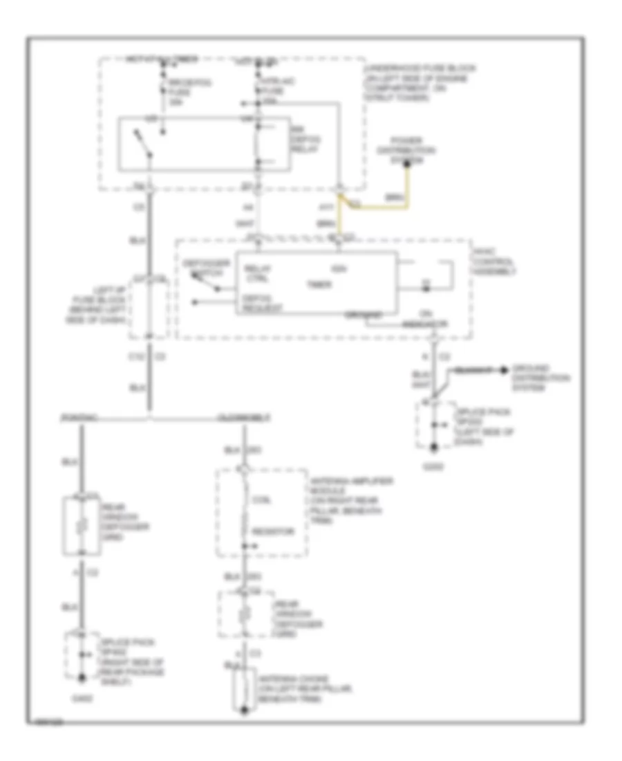
List of elements for Defoggers Wiring Diagram for Oldsmobile Alero GX 2003:
- A11
- Antenna amplifier module (on right rear pillar, beneath trim)
- Antenna choke (on left rear pillar, beneath trim)
- C c2
- C1 a
- C1 c2
- C2 a
- C3 a
- C3 c12
- Coil
- Defog request
- Defogger switch
- G202
- G402
- Ground
- Ground distribution system
- Hot at all times
- Hot in on
- Htr-a/c fuse 10a
- Hvac control assembly
- Ign
- K c2
- Left i/p fuse block (behind left side of dash)
- Oldsmobile
- On indicator
- Pontiac
- Power distribution system
- Rear window defogger grid
- Relay ctrl
- Resistor
- Rr defog fuse 30a
- Rr defog relay
- Splice pack sp202 (left side of dash)
- Splice pack sp402 (right side of rear package shelf)
- Timer
- Underhood fuse block (in left side of engine compartment, on strut tower)
 Čeština
 Dansk
Dansk Deutsch
 Ελληνικά
 English
 English
 Español
 Suomi
Suomi Français
 Français
 עברית
עברית Hrvatski
 Magyar
 Italiano
 日本語
日本語 한국어
한국어 Nederlands
 Polski
 Português
 Português
 Română
 Slovenčina
 Slovenščina
 Svenska
 Türkçe
 中文 (中国)
 Русский