
 Čeština
 Dansk
Dansk Deutsch
 Ελληνικά
 English
 English
 Español
 Suomi
Suomi Français
 Français
 עברית
עברית Hrvatski
 Magyar
 Italiano
 日本語
日本語 한국어
한국어 Nederlands
 Polski
 Português
 Português
 Română
 Русский
 Slovenščina
 Svenska
 Türkçe
 中文 (中国)

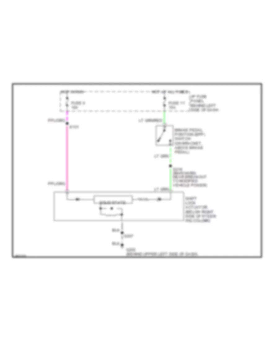
SHIFT INTERLOCKS
Shift Interlock Wiring Diagram for Ford Econoline E150 1998
List of elements for Shift Interlock Wiring Diagram for Ford Econoline E150 1998:

AIR CONDITIONINGCOMPUTER DATA LINESCRUISE CONTROLANTI-LOCK BRAKESEXTERIOR LIGHTSINTERIOR LIGHTSHEADLIGHTSENGINE PERFORMANCEGROUND DISTRIBUTIONPOWER DISTRIBUTIONPOWER DOOR LOCKSINSTRUMENT CLUSTERPOWER MIRRORSHORNPOWER SEATSRADIOSUPPLEMENTAL RESTRAINTSPOWER WINDOWSTRANSMISSIONWARNING SYSTEMSSHIFT INTERLOCKSSTARTING/CHARGINGWIPER/WASHER