SUPPLEMENTAL RESTRAINTS
Supplemental Restraint Wiring Diagram, with Passenger Deactivation for Ford Ranger 1997

List of elements for Supplemental Restraint Wiring Diagram, with Passenger Deactivation for Ford Ranger 1997:
- (left side of i/p) data link connector (dlc)
- (main harn, behind right cowl panel)
- (main harn, near generic electronic module (gem) breakout)
- (main harn, near radio breakout)
- (main harn, near rear anti-lock brake sys module breakout)
- Air bag diagnostic monitor (behind right side of cowl panel)
- Air bag fuse 7 10a
- Air bag ind
- Air bag indicator control
- C216
- C250
- C251
- Clock- spring assembly
- Data link
- Driver's air bag
- Drvr air bag
- Engine compartment fuse/relay box (left rear of engine compt)
- Fuse 15 7.5a
- Fuse 6 7.5a
- G104 (top center of left fender apron)
- G108 (left upper radiator support)
- Gnd
- Hot at all times
- Hot in run
- Hot in run or start
- I/p fuse panel (below left side of i/p)
- Instrument cluster
- L crash sens
- Left primary crash sensor (left front upper radiator support)
- Nca
- Off
- Pass air bag
- Passenger's air bag
- Passive airbag deactivation (pad) module
- Pwr (bat)
- Pwr (run)
- R crash sens
- Right primary crash sensor (right front upper radiator support)
- S200
- S205
- S209
- S225
- S250 (main harn, near i/p fuse panel breakout)
- Shorting bar
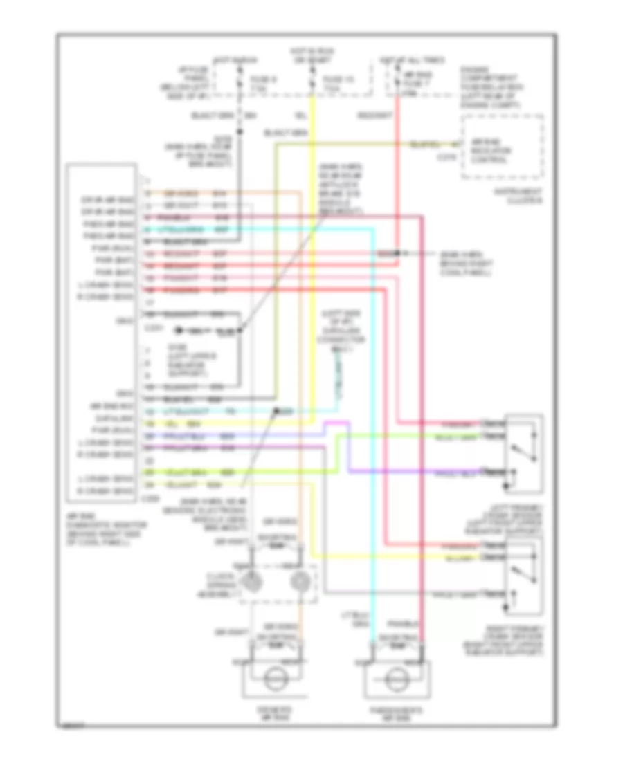
Supplemental Restraint Wiring Diagram, without Passenger Deactivation for Ford Ranger 1997
List of elements for Supplemental Restraint Wiring Diagram, without Passenger Deactivation for Ford Ranger 1997:
- (left side of i/p) data link connector (dlc)
- (main harn, behind right cowl panel)
- (main harn, near generic electronic module (gem) breakout)
- (main harn, near rear anti-lock brake sys module breakout)
- Air bag diagnostic monitor (behind right side of cowl panel)
- Air bag fuse 7 10a
- Air bag ind
- Air bag indicator control
- C216
- C250
- C251
- Clock- spring assembly
- Data link
- Driver's air bag
- Drvr air bag
- Engine compartment fuse/relay box (left rear of engine compt)
- Fuse 15 7.5a
- Fuse 6 7.5a
- G108 (left upper radiator support)
- Gnd
- Hot at all times
- Hot in run
- Hot in run or start
- I/p fuse panel (below left side of i/p)
- Instrument cluster
- L crash sens
- Left primary crash sensor (left front upper radiator support)
- Nca
- Pass air bag
- Passenger's air bag
- Pwr (bat)
- Pwr (run)
- R crash sens
- Right primary crash sensor (right front upper radiator support)
- S200
- S205
- S225
- S250 (main harn, near i/p fuse panel breakout)
- Shorting bar