CRUISE CONTROL
4.2L
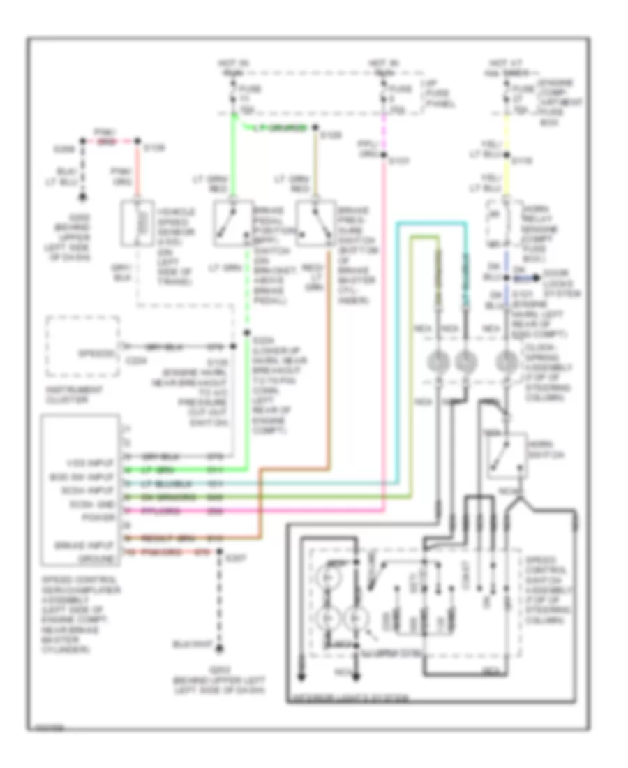
4.2L, Cruise Control Wiring Diagram for Ford Econoline E150 1998
 https://portal-diagnostov.com/license.html
Automotive Electricians Portal FZCO
Automotive Electricians Portal FZCO
https://portal-diagnostov.com/license.html
https://portal-diagnostov.com/license.html
Automotive Electricians Portal FZCO
Automotive Electricians Portal FZCO
List of elements for 4.2L, Cruise Control Wiring Diagram for Ford Econoline E150 1998:
- (engine harn, left rear of eng compt)
- Accel set/
- Boo sw input
- Brake input
- Brake pedal position (bpp) switch (on bracket, above brake pedal)
- Brake pres- sure switch (bottom of brake master cyl- inder)
- C224
- Clock- spring assembly (top of steering column)
- Coast
- Door locks system
- Engine comp- artment fuse box
- Fuse 10a
- Fuse 15a
- G202 (behind upper left left side of dash)
- G202 (behind upper left side of dash)
- Ground
- Horn relay (engine compt fuse box)
- Horn switch
- Hot at all times
- Hot in run
- I/p fuse panel
- Illumination
- Instrument cluster
- Interior lights system
- Nca
- Off
- Ohms
- Power
- Resume
- S116
- S129
- S131
- S135 (engine harn, near breakout to a/c pressure cut-out switch)
- S139
- S207
- S224 (lower i/p harn, near breakout to 76 pin conn, left rear of engine compt)
- S268
- Scsa gnd
- Scsa input
- Speed control servo/amplifier assembly (left side of engine compt, near brake master cylinder)
- Speed control switch assembly (top of steering column)
- Speedo
- Vehicle speed sensor (vss) (on left side of trans)
- Vss input
4.6L
4.6L, Cruise Control Wiring Diagram for Ford Econoline E150 1998
 https://portal-diagnostov.com/license.html
Automotive Electricians Portal FZCO
Automotive Electricians Portal FZCO
https://portal-diagnostov.com/license.html
https://portal-diagnostov.com/license.html
Automotive Electricians Portal FZCO
Automotive Electricians Portal FZCOList of elements for 4.6L, Cruise Control Wiring Diagram for Ford Econoline E150 1998:
- (engine harn, left rear of eng compt)
- Accel set/
- Boo sw input
- Brake input
- Brake pedal position (bpp) switch (on bracket, above brake pedal)
- Brake pres- sure switch (bottom of brake master cyl- inder)
- C224
- Clock- spring assembly (top of steering column)
- Coast
- Door locks system
- Engine comp- artment fuse box
- Fuse 10a
- Fuse 15a
- G202 (behind upper left left side of dash)
- G202 (behind upper left side of dash)
- Ground
- Horn relay (engine compt fuse box)
- Horn switch
- Hot at all times
- Hot in run
- I/p fuse panel
- Illumination
- Instrument cluster
- Interior lights system
- Nca
- Off
- Ohms
- Power
- Resume
- S116
- S129
- S131
- S135 (engine harn, near breakout to a/c pressure cut-out switch)
- S139
- S207
- S224 (lower i/p harn, near breakout to 76 pin conn, left rear of engine compt)
- S268
- Scsa gnd
- Scsa input
- Speed control servo/amplifier assembly (left side of engine compt, near brake master cylinder)
- Speed control switch assembly (top of steering column)
- Speedo
- Vehicle speed sensor (vss) (on left side of trans)
- Vss input
5.4L
5.4L, Cruise Control Wiring Diagram for Ford Econoline E150 1998
 https://portal-diagnostov.com/license.html
Automotive Electricians Portal FZCO
Automotive Electricians Portal FZCO
https://portal-diagnostov.com/license.html
https://portal-diagnostov.com/license.html
Automotive Electricians Portal FZCO
Automotive Electricians Portal FZCOList of elements for 5.4L, Cruise Control Wiring Diagram for Ford Econoline E150 1998:
- (engine harn, left rear of eng compt)
- Accel set/
- Boo sw input
- Brake input
- Brake pedal position (bpp) switch (on bracket, above brake pedal)
- Brake pres- sure switch (bottom of brake master cyl- inder)
- C224
- Clock- spring assembly (top of steering column)
- Coast
- Door locks system
- Engine comp- artment fuse box
- Fuse 10a
- Fuse 15a
- G202 (behind upper left left side of dash)
- G202 (behind upper left side of dash)
- Ground
- Horn relay (engine compt fuse box)
- Horn switch
- Hot at all times
- Hot in run
- I/p fuse panel
- Illumination
- Instrument cluster
- Interior lights system
- Nca
- Off
- Ohms
- Power
- Resume
- S116
- S129
- S131
- S135 (engine harn, near breakout to a/c pressure cut-out switch)
- S139
- S207
- S224 (lower i/p harn, near breakout to 76 pin conn, left rear of engine compt)
- S268
- Scsa gnd
- Scsa input
- Speed control servo/amplifier assembly (left side of engine compt, near brake master cylinder)
- Speed control switch assembly (top of steering column)
- Speedo
- Vehicle speed sensor (vss) (on left side of trans)
- Vss input

 Čeština
 Dansk
Dansk Deutsch
 Ελληνικά
 English
 English
 Español
 Suomi
Suomi Français
 Français
 עברית
עברית Hrvatski
 Magyar
 Italiano
 日本語
日本語 한국어
한국어 Nederlands
 Polski
 Português
 Português
 Română
 Русский
 Slovenčina
 Slovenščina
 Svenska
 中文 (中国)
