POWER DISTRIBUTION
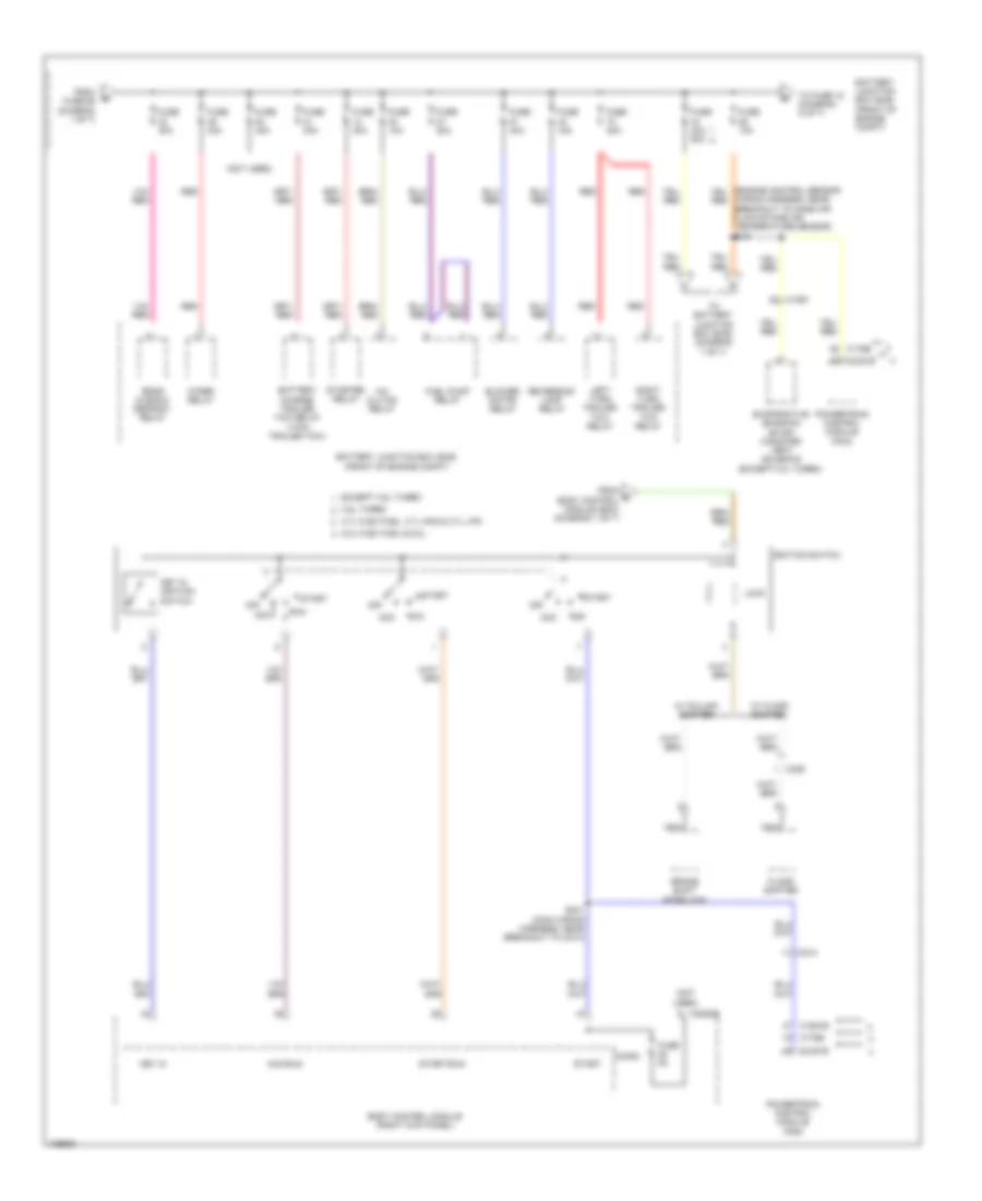
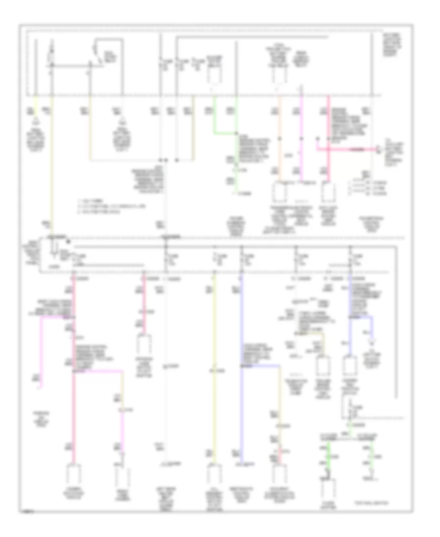
Power Distribution Wiring Diagram (1 of 7) for Ford F-150 XL 2014
 https://portal-diagnostov.com/license.html
Automotive Electricians Portal FZCO
Automotive Electricians Portal FZCO
https://portal-diagnostov.com/license.html
https://portal-diagnostov.com/license.html
Automotive Electricians Portal FZCO
Automotive Electricians Portal FZCO
List of elements for Power Distribution Wiring Diagram (1 of 7) for Ford F-150 XL 2014:
- (alternator rectifier system wiring harness, in breakout to fusible link e) s143
- (engine control sensor wiring harness, in breakout red
- (engine control sensor wiring harness, in breakout to fusible link a) s109
- (front of engine compt) battery junction box (bjb)
- (main wiring harness, near breakout to g203) (w/ adjustable pedal/ tilt/telescope column) s212
- 6.2l
- Anti-lock brake system (abs) module
- Audio control module (acm)
- Automatic a/c
- Base
- Battery
- Body control module (right kick panel)
- C1035a
- C1035b
- C1463a
- C1617a
- C1617b
- C192
- C2108
- C211
- C213
- C215
- C2280a
- C2280g
- C228a
- C2357
- C2371b
- C2414b
- C264
- C290a
- C294a
- C312
- C3313b
- Crew chief
- Data link connector (dlc)
- Eatc hvac module
- Emtc hvac module
- Except 6.2l
- Except base
- From battery junction box (bjb) (diagram 1 of 7)
- Front cigar lighter
- Fuse (except 6.2l) 10a
- Fuse 10a
- Fuse 15a
- Fuse 20a
- Fuse 30a
- Fuse 40a
- Fuse 60a
- G203 (left side of dash)
- Generator
- Generator current sensor
- High current battery junction box (right front corner of engine compt)
- Inline fuse (center of dash)
- Instrument panel cluster (ipc)
- Instrument panel power point
- Integrated wheel end (iwe) solenoid (w/ electronic shift on the fly)
- Left headlamp (w/ hid)
- Manual a/c
- Mega fuse 125a
- Mega fuse 250a
- Nca
- Passenger side front seat control switch (w/ 10-way power seat)
- Power running board (prb) module
- Power steering control module
- Premium audio
- Red
- Right headlamp (w/ hid)
- S142 (alternator rectifier system wiring harness, in breakout to fusible link e)
- S144 (alternator rectifier system wiring harness, in breakout to fusible link e)
- S272 (crew chief) (t-box jumper wiring harness, near breakout to c2108)
- Starter motor
- Steering column control module (sccm) (w/ adjustable pedal/ tilt/telescope column)
- Telematics module (crew chief)
- To dc/ac inverter module (diagram 3 of 7)
- To fuse 27 (diagram 3 of 7)
- To fuse 32 (diagram 2 of 7)
- To fusible link a) s110
- To ignition switch (diagram 2 of 7)
- To splice s110 (diagram 1 of 7)
- Trailer brake control (tbc) module
- Transfer case control module (tccm) (w/ electronic shift on the fly)
- W/ column shifter
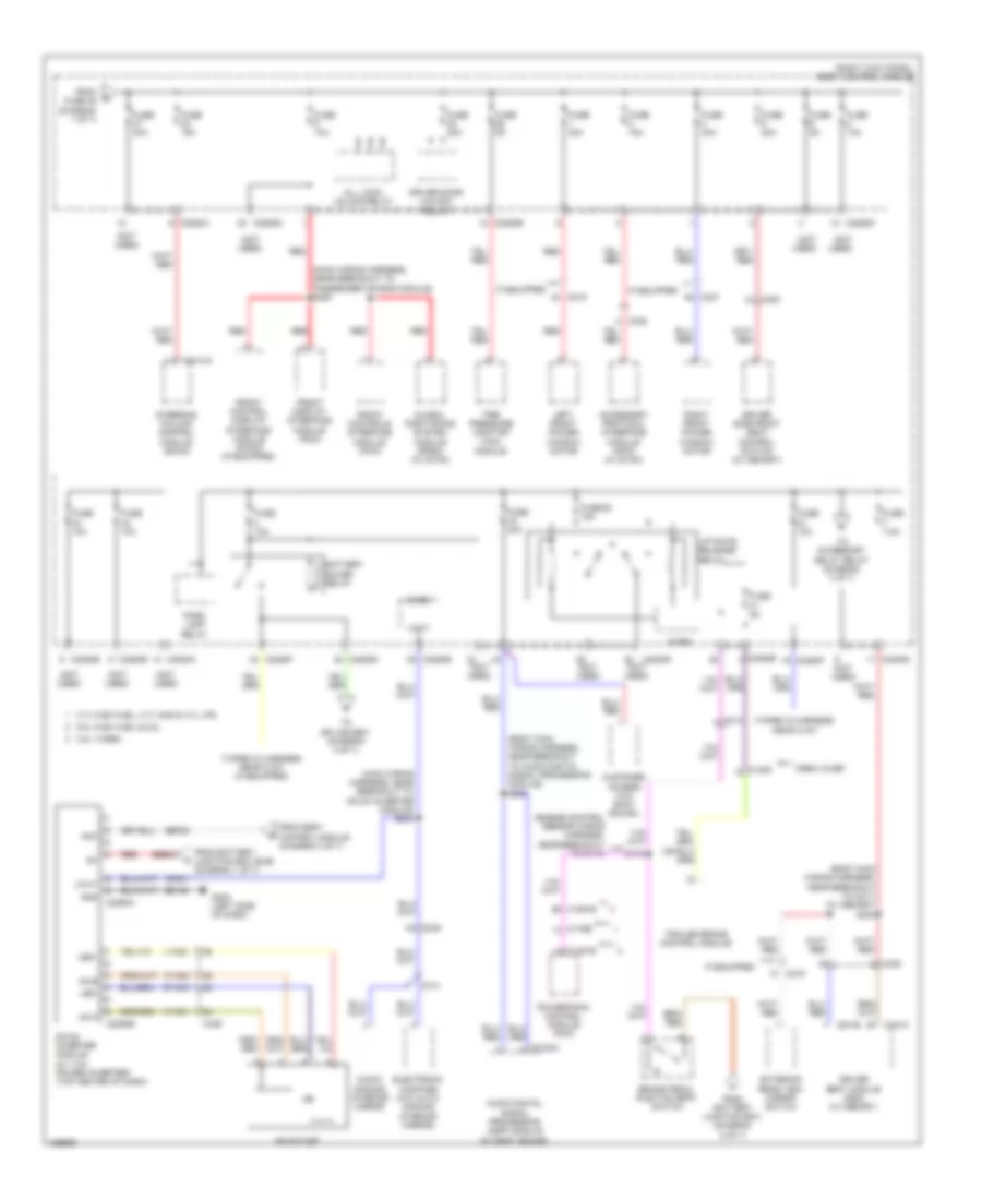
Power Distribution Wiring Diagram (2 of 7) for Ford F-150 XL 2014
 https://portal-diagnostov.com/license.html
Automotive Electricians Portal FZCO
Automotive Electricians Portal FZCO
https://portal-diagnostov.com/license.html
https://portal-diagnostov.com/license.html
Automotive Electricians Portal FZCO
Automotive Electricians Portal FZCOList of elements for Power Distribution Wiring Diagram (2 of 7) for Ford F-150 XL 2014:
- (not used)
- 3.5l turbo
- 3.7l flex fuel, 3.7l cng & 3.7l lpg
- 5.0l flex fuel & 6.2l
- A/c clutch relay
- Acc
- Acc/run
- Battery charge trailer tow relay (7-pin trailer tow)
- Battery junction box (bjb) (front of engine compt)
- Blower motor relay
- Body control module (right kick panel)
- Brake shift interlock
- C1381b
- C1551b
- C1581
- C175b
- C214
- C2280b
- C329
- Evaporative emission (evap) canister vent solenoid (except 3.5l turbo)
- Except 3.5l turbo
- Floor shifter
- From e body control module (bcm) (diagram 1 of 7)
- From fuse 65 (diagram 1 of 7)
- Fuel pump relay
- Fuse 10a
- Fuse 15a
- Fuse 20a
- Fuse 30a
- Fuse 40a
- Fuse 40a 50a
- Fuse 5a
- Ignition switch
- Key in
- Key in ignition switch
- Left turn trailer tow relay
- Lock
- Micro
- Nca
- Off
- Powertrain control module (pcm)
- Rear window defrost relay
- Red
- Reversing lamp relay
- Right turn trailer tow relay
- Run
- S241 (main wiring harness, near breakout to c213)
- Start
- Start/run
- Starter relay
- To battery junction box (bjb) (diagram 7 of 7)
- To fuse 18 (diagram 5 of 7)
- W/ column shifter
- W/ floor shifter
- Wiper relay
- Wiring harness, near breakout to mass air flow/intake air temperature sensor) s101
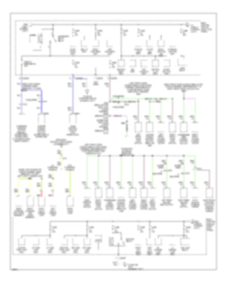
Power Distribution Wiring Diagram (3 of 7) for Ford F-150 XL 2014
 https://portal-diagnostov.com/license.html
Automotive Electricians Portal FZCO
Automotive Electricians Portal FZCO
https://portal-diagnostov.com/license.html
https://portal-diagnostov.com/license.html
Automotive Electricians Portal FZCO
Automotive Electricians Portal FZCOList of elements for Power Distribution Wiring Diagram (3 of 7) for Ford F-150 XL 2014:
- (body main wiring harness, near breakout to audio digital signal processing module) s324
- (body main wiring harness, near breakout to c311) (w/ memory) s354
- (engine control sensor wiring harness, near breakout to c110)
- (main wiring harness, near breakout to dc/ac inverter module) s244
- (main wiring harness, near breakout to passenger air bag module) s220
- (not used)
- (right kick panel) body control module
- (taped in harness near c127)
- (taped in harness near c127) (if equipped)
- 3.5l turbo
- 3.7l flex fuel, 3.7l cng & 3.7l lpg
- 5.0l flex fuel & 6.2l
- Ac outlet
- Ac-a
- Ac-b
- Acc
- Accessory protocol interface module (apim) (w/ sync)
- All lock/ unlock relay
- Audio digital signal processing (dsp) module (w/ sony sound)
- Audio- dimming interior mirror
- Battery saver relay
- Brake pedal position (bpp) switch
- C1208
- C1381b
- C1551b
- C175b
- C214
- C219
- C2280a
- C2280b
- C2280d
- C2280e
- C2280f
- C2293a
- C2293b
- C237
- C238
- C2414a
- C248
- C300
- C314
- C3154c
- C329
- C341b
- C341c
- Cbp38
- Crew chief
- Customer access (w/o sony sound)
- Dc/ac inverter module (w/ 110v power inverter) (top center of dash)
- Driver door unlock relay
- Driver seat module (dsm) (w/ memory)
- Driver side front seat control switch (w/ memory)
- Electronic compass (w/o auto- dimming interior mirror)
- Exterior rear view mirror switch
- From battery junction box (bjb) (diagram 1 of 7)
- From battery junction box (diagram 5 of 7)
- From body control module (diagram 4 of 7)
- From fuse 46 (diagram 1 of 7)
- Front control display interface module (fcdim) (if equipped)
- Front controls interface module (fcim)
- Front display interface module (fdim)
- Fuse 10a
- Fuse 15a
- Fuse 20a
- Fuse 25 15a
- Fuse 30a
- Fuse 5a
- Fuse 7.5a
- G203 (left side of dash)
- Gd138
- Global positioning system module (gpsm) (w/ sync)
- Gnd
- Hya01
- Hya02
- If equipped
- Led+
- Led-
- Left front power window motor
- Liftgate release relay
- Lin 01
- Lya03
- Micro
- Park lamp relay
- Powertrain control module (pcm)
- Red
- Right front power window motor
- Rya03
- S112
- Sbb33
- Steering column control module (sccm)
- Tire pressure monitor (tpm) module
- To accessory delay relay (diagram 4 of 7)
- To splice s901 (diagram 4 of 7)
- Trailer brake control module
- Vdn01
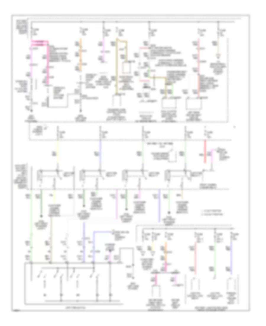
Power Distribution Wiring Diagram (4 of 7) for Ford F-150 XL 2014
 https://portal-diagnostov.com/license.html
Automotive Electricians Portal FZCO
Automotive Electricians Portal FZCO
https://portal-diagnostov.com/license.html
https://portal-diagnostov.com/license.html
Automotive Electricians Portal FZCO
Automotive Electricians Portal FZCOList of elements for Power Distribution Wiring Diagram (4 of 7) for Ford F-150 XL 2014:
- (dome lamp connector wiring harness, near breakout to left left vanity mirror lamp) s901
- (left front door window regulator wiring harness, near breakout to driver front door side impact sensor) s504
- (left front door window regulator wiring harness, near breakout to exterior rear view mirror switch)
- (not used)
- (right front door window regulator wiring harness, near breakout to right front door lock switch) s605
- 3rd row seat (fet)
- Accessory delay relay
- Audio control module (acm) (base audio)
- Auto- dimming interior mirror
- Back- lighting led (fet)
- Body control module (right kick panel)
- Bsi (fet)
- C219
- C2280a
- C2280b
- C2280d
- C2280f
- C237
- C290a
- C314
- C315
- C316
- C327
- C535b
- Circuit breaker 48 30a
- Electronic compass (w/o auto- dimming interior mirror)
- Fog lamp relay
- From body control module (bcm) (diagram 3 of 7)
- From fuse 22 (diagram 4 of 7)
- From fuse 7 (diagram 3 of 7)
- Front dome lamp
- Front interior/ map lamps assembly
- Fuse 10a
- Fuse 15a
- Fuse 20a
- Horn relay
- If equipped
- Interior lighting (fet)
- Keypad illum (fet)
- Left front door lock switch
- Left front power window motor
- Left high beam (fet)
- Left low beam (fet)
- Left rear heated seat switch
- Left vanity mirror lamp
- Lf turn lamp (fet)
- Lh corner lamp (fet)
- Lr stop/ turn lamp (fet)
- Lr turn lamp (fet)
- Master window control switch (regular cab)
- Master window control switch (super crew & super cab)
- Micro
- Overhead console switch assembly (super crew, super cab & w/ power sliding rear window)
- Passenger side window control switch
- Pcm wake up (fet)
- Puddle lamp (fet)
- Rear interior/ map lamps assembly
- Red
- Rev lp (fet)
- Rf turn lamp (fet)
- Rh corner lamp (fet)
- Right front door lock switch
- Right front power window motor
- Right high beam (fet)
- Right low beam (fet)
- Right rear heated seat switch
- Right vanity mirror lamp
- Roof opening panel module
- Rr stop/ turn lamp (fet)
- Rr turn lamp (fet)
- Run/acc relay
- S308 (regular cab: body main wiring harness, near breakout to c312) (super cab: body main wiring harness, near breakout to c313)
- Start button (fet)
- Stop/ chmsl (fet)
- Super crew
- Telescopic exterior rearview mirror switch
- To dc/ac inverter module (diagram 3 of 7)
- To fuse 47 (diagram 4 of 7)
- To splice s157 (diagram 7 of 7)
- W/ overhead console
- W/o overhead console
- White led (fet)
Power Distribution Wiring Diagram (5 of 7) for Ford F-150 XL 2014
 https://portal-diagnostov.com/license.html
Automotive Electricians Portal FZCO
Automotive Electricians Portal FZCO
https://portal-diagnostov.com/license.html
https://portal-diagnostov.com/license.html
Automotive Electricians Portal FZCO
Automotive Electricians Portal FZCOList of elements for Power Distribution Wiring Diagram (5 of 7) for Ford F-150 XL 2014:
- (customer access taped to harness near c214)
- (main wiring harness, in breakout to front display interface module)
- (passenger seat wiring harness, in breakout to heated seat module) s341
- 2wd
- 4wd
- Auxiliary battery junction box (w/ svt raptor) (left rear corner of engine compt)
- Battery junction box (bjb) (front of engine compt)
- C210
- C212
- C213
- C215
- C228a
- C2371b
- C2613b
- C311
- C312
- C313
- C3162b
- C3205
- C3265a f
- C329
- C341a
- Console 1 power point (w/ floor shifter)
- Console 2 power point (w/ column shifter)
- Console 2 power point (w/ floor shifter)
- Driver seat module (dsm)
- Driver side front seat control switch (w/ 6-way power seat)
- Dual climate controlled seat module (dcsm) (if equipped)
- Eatc hvac module (w/ heated seats)
- Electronic locking differential (eld) module (if equipped)
- From fuse 26 (diagram 2 of 7)
- From splice s118 (diagram 6 of 7)
- From splice s243 (diagram 6 of 7)
- Front camera washer relay
- Fuse 10a
- Fuse 15a
- Fuse 20a
- Fuse 25a
- Fuse 30a
- Fuse 40a 50a
- Fuse 5a
- G102 (left front of engine compt)
- G201 (right kick panel)
- G203 (left side of dash)
- High fan control (hfc) relay
- Interior lights system
- Left rear heated seat module (super crew)
- Low fan control (lfc) relay
- Parking lamp trailer tow relay
- Power mirror fold module (if equipped)
- Red
- Roof opening panel module (if equipped)
- S222
- S246 (w/ rear power point) (engine control sensor wiring harness, near breakout to c214)
- S329
- S329 (w/ moon roof)
- S370 (driver side crew cab rear seat wiring assembly, near breakout to c3205)
- Sunload sensor)
- To battery junction box (bjb) (diagram 6 of 7)
- To brake pedal position (bpp) switch (diagram 3 of 7)
- Transfer case control module (tccm) (w/ electronic shift on the fly)
- Upfitter relay 1
- Upfitter relay 2
- Upfitter relay 3
- Upfitter relay 4
- Upfitter switch
- W/ memory
- W/ svt raptor
- W/o memory
- W/o svt raptor
Power Distribution Wiring Diagram (6 of 7) for Ford F-150 XL 2014
 https://portal-diagnostov.com/license.html
Automotive Electricians Portal FZCO
Automotive Electricians Portal FZCO
https://portal-diagnostov.com/license.html
https://portal-diagnostov.com/license.html
Automotive Electricians Portal FZCO
Automotive Electricians Portal FZCOList of elements for Power Distribution Wiring Diagram (6 of 7) for Ford F-150 XL 2014:
- (7-pin trailer tow) battery charge trailer tow relay
- (body main wiring harness, near breakout to g202) (w/ rear view camera) s203
- (engine control sensor wiring harness, near breakout to mass air flow/intake air temperature sensor) s118
- (main wiring harness, near breakout to body control module) s242
- (main wiring harness, near breakout to passenger air bag module) (w/ svt raptor) s243
- (not used)
- (t-box jumper wiring harness, near breakout to c2108) (crew chief) s274
- (w/ front camera) s119
- 2wd
- 3.5l turbo
- 3.7l flex fuel, 3.7l cng & 3.7l lpg
- 5.0l flex fuel & 6.2l
- Anti-lock brake system (abs) module
- Battery junction box (bjb) (front of engine compt)
- Blower motor relay
- Body control module (right kick panel)
- C1381b
- C139
- C145
- C1463b
- C1551b
- C175b
- C2108
- C212
- C2280b
- C2280d
- C2280e
- C2280f
- C2371a
- C238
- C2613a
- C264
- C310a
- C312
- C3162b
- C3205
- C329
- Camera switching module
- Crew chief
- Electronic locking differental (eld) module
- Floor shifter
- From battery junction box (bjb) (diagram 5 of 7)
- Front video camera
- Fuse 10a
- Fuse 5a
- Fuse 7.5a
- Hazard/ pad/ traction switch
- Hill descent control switch (w/ svt raptor)
- Left rear heated seat module (super crew)
- Micro
- Nca
- Occupant classification system module (ocsm)
- Off-road mode switch (w/ svt raptor)
- Parking aid module (pam)
- Power steering control module (pscm)
- Powertrain control module (pcm)
- Rear window defrost relay
- Restraints control module (rcm)
- Run/ start (fet)
- Run/ start relay
- S156 (engine control sensor wiring harness, near breakout to engine cooling fan motor 1)
- S161 (engine control sensor wiring harness, near breakout to engine cooling fan motor 1)
- Telematics module (crew chief)
- To auxiliary battery junction box (diagram 5 of 7)
- To upfitter switch (diagram 5 of 7)
- Tow haul switch
- Trailer brake control (tbc) module
- Transfer case control module (tccm) (w/ electronic shift on the fly)
- W/ column shifter
- W/ floor shifter
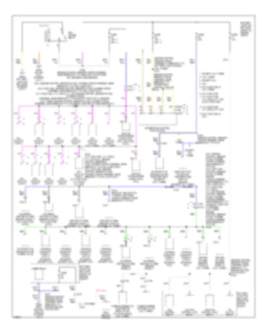
Power Distribution Wiring Diagram (7 of 7) for Ford F-150 XL 2014
 https://portal-diagnostov.com/license.html
Automotive Electricians Portal FZCO
Automotive Electricians Portal FZCO
https://portal-diagnostov.com/license.html
https://portal-diagnostov.com/license.html
Automotive Electricians Portal FZCO
Automotive Electricians Portal FZCOList of elements for Power Distribution Wiring Diagram (7 of 7) for Ford F-150 XL 2014:
- (6.2l: engine control sensor & fuel charge wiring harness, near breakout to c133) (5.0l flex fuel: control sensor & fuel charge engine wiring harness, near breakout to fuel injector 1) (3.7l flex fuel, 3.7l cng & 3.7l lpg: engine control sensor & fuel charge wiring harness, near breakout to camshaft position 21 sensor) (3.5l turbo: engine control sensor & fuel charge wiring harness, near breakout to c180) s136
- (6.2l: engine control sensor & fuel charge wiring harness, near breakout to fuel injector 1) (5.0l flex fuel: engine control sensor & fuel charge wiring harness, near breakout to fuel injector 4) (3.7l flex fuel, 3.7l cng & 3.7l lpg: engine control sensor & fuel
- (engine control sensor wiring harness, in breakout to battery junction box) (3.5l turbo) s121
- (engine control sensor wiring harness, near breakout to engine cooling fan motor 1) s105
- (engine control sensor wiring harness, near breakout to powertrain control module) s103
- 3.5l turbo
- 3.7l cng & 3.7l lpg
- 3.7l cng & 3.7l lpg & 5.0l flex fuel
- 3.7l flex fuel,
- 5.0l flex fuel
- 5.0l flex fuel & 3.5l turbo
- 5.0l flex fuel & 6.2l
- 6.2l
- A/c clutch relay
- Battery junction box (bjb) (front of engine compt)
- C1010
- C136
- C1381b
- C140
- C146
- C1551b
- C1581
- C175b
- C212
- C315
- Charge wiring harness, near breakout to camshaft position 21 sensor) (3.5l turbo: engine control sensor & fuel charge wiring harness, near breakout to universal heated oxygen sensor 21)
- Coil on plug (cop) 1
- Coil on plug (cop) 2
- Coil on plug (cop) 3
- Coil on plug (cop) 4
- Coil on plug (cop) 4 (3.7l flex fuel, 3.7l cng & 3.7l lpg)
- Coil on plug (cop) 5
- Coil on plug (cop) 5 (3.5l turbo)
- Coil on plug (cop) 6
- Coil on plug (cop) 6 (3.5l turbo)
- Coil on plug (cop) 7
- Coil on plug (cop) 8
- Evaporative emission (evap) canister vent solenoid (3.5l turbo)
- Evaporative emission (evap) purge valve
- Except 3.5l turbo
- Except 6.2l
- Fan control relay
- From battery junction box (bjb) (diagram 2 of 7)
- From body control module (diagram 4 of 7)
- From splice s101 (diagram 2 of 7)
- Fuse 10a
- Fuse 15a 20a
- Fuse 15a 25a
- Fuse 20a
- Fuse 5a
- Heated oxygen sensor (ho2s) 12 (3.5l turbo)
- Heated oxygen sensor (ho2s) 12 (except 3.5l turbo)
- Heated oxygen sensor (ho2s) 22 (3.5l turbo)
- Heated oxygen sensor (ho2s) 22 (except 3.5l turbo)
- High fan control (hfc) relay
- Ignition transformer capacitor 1 (5.0l flex fuel & 6.2l)
- Ignition transformer capacitor 2 (6.2l)
- Low fan control (lfc) relay
- Mass air flow/ intake air temperature (maf/iat) sensor (except 3.5l turbo)
- Nca
- Pcm power relay
- Powertrain control module (pcm)
- Rain sensor module
- S125 (engine control sensor wiring harness, near breakout to mass air flow/intake air temperature sensor)
- S129 (engine control sensor wiring harness, near breakout to c144)
- S135 (3.7l flex fuel, 3.7l cng & 3.7l lpg & 6.2l: engine control sensor & fuel charge wiring harness, near breakout to fuel injector 6) (5.0l flex fuel: engine control sensor & fuel charge wiring harness, near breakout to coil on plug 7)
- S139
- S148 (backup lamp switch to rear lamp feed wiring harness, near breakout to c140)
- S157 (engine control sensor wiring harness, near breakout to engine cooling fan motor 1)
- Turbocharger (tc) wastegate regulating valve solenoid (3.5l turbo)
- Turbocharger bypass valve (3.5l turbo)
- Universal heated oxygen sensor (ho2s) 11
- Universal heated oxygen sensor (ho2s) 11 (5.0l flex fuel & 6.2l)
- Universal heated oxygen sensor (ho2s) 21
- Universal heated oxygen sensor (ho2s) 21 (5.0l flex fuel & 6.2l)
- Variable camshaft timing 11 (vct11) solenoid (6.2l)
- Variable camshaft timing 11 (vct11) solenoid (except 6.2l)
- Variable camshaft timing 12 (vct12) solenoid (except 6.2l)
- Variable camshaft timing 21 (vct21) solenoid (6.2l)
- Variable camshaft timing 21 (vct21) solenoid (except 6.2l)
- Variable camshaft timing 22 (vct22) solenoid (except 6.2l)
- Wiper relay

 Čeština
 Dansk
Dansk Deutsch
 Ελληνικά
 English
 English
 Español
 Suomi
Suomi Français
 Français
 עברית
עברית Hrvatski
 Magyar
 Italiano
 日本語
日本語 한국어
한국어 Nederlands
 Polski
 Português
 Português
 Română
 Русский
 Slovenčina
 Slovenščina
 Svenska
 中文 (中国)
