WARNING SYSTEMS
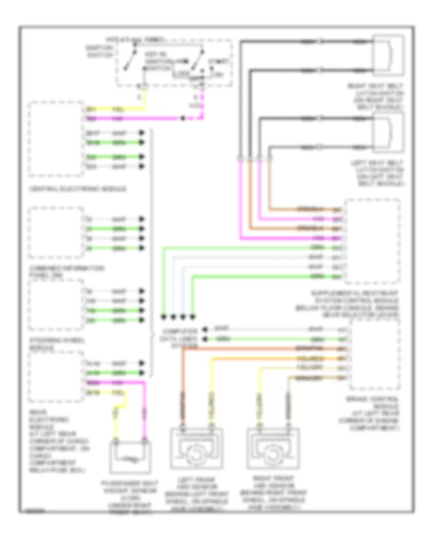
Warning Systems Wiring Diagram for Volvo V70 R 2004
List of elements for Warning Systems Wiring Diagram for Volvo V70 R 2004:
- A14
- A16
- Acc
- B17
- B18
- B19
- B20
- Brake control module (at left rear corner of engine compartment)
- Central electronic module
- Combined information panel dim
- Computer data lines system
- Hot at all times
- Ignition switch
- Key-in ignition switch
- Left front abs sensor (behind left front wheel, on spindle /hub assembly)
- Left seat belt latch switch (on left seat belt buckle)
- Lock off
- Nca
- Passenger seat weight sensor (xc90) (under right front seat)
- Rear electronic module (at left rear corner of cargo compartment, on cargo compartment relay/fuse box)
- Right front abs sensor (behind right front wheel, on spindle /hub assembly)
- Right seat belt latch switch (on right seat belt buckle)
- Start
- Steering wheel module
 English