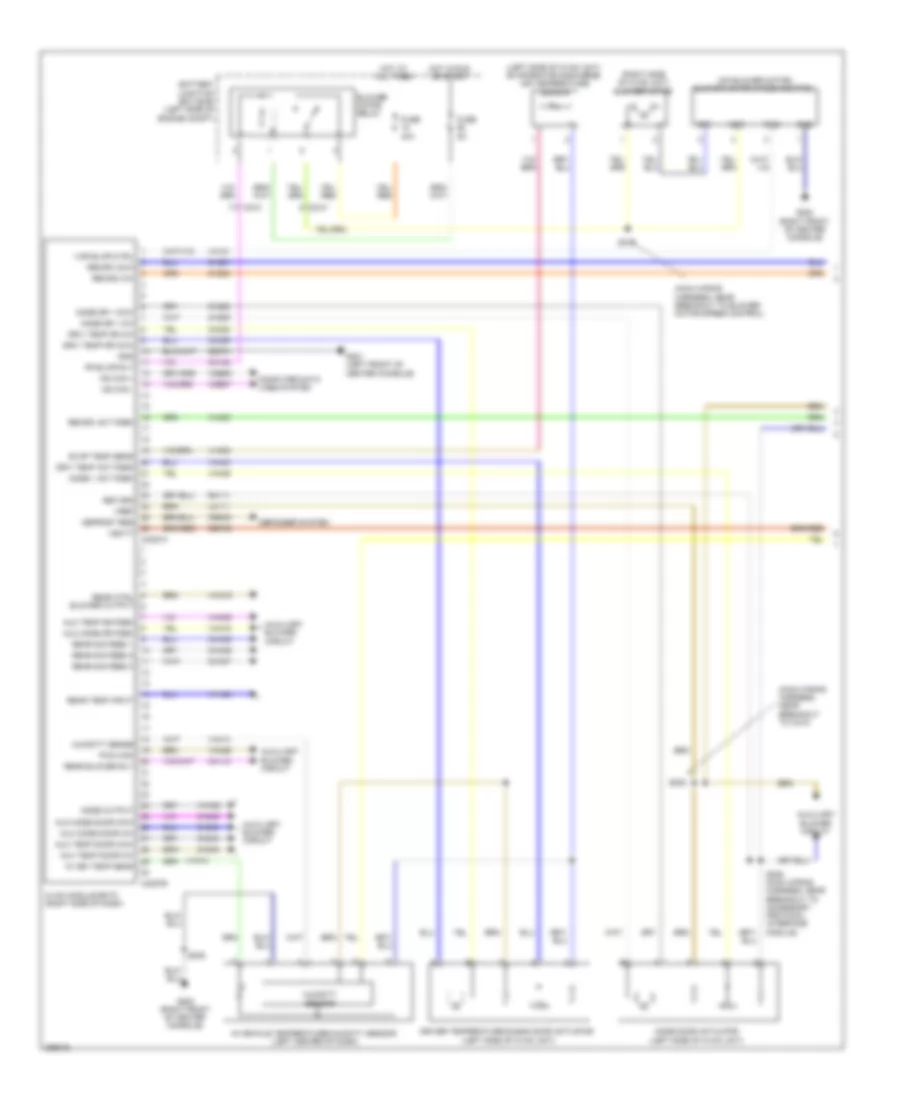
AIR CONDITIONING
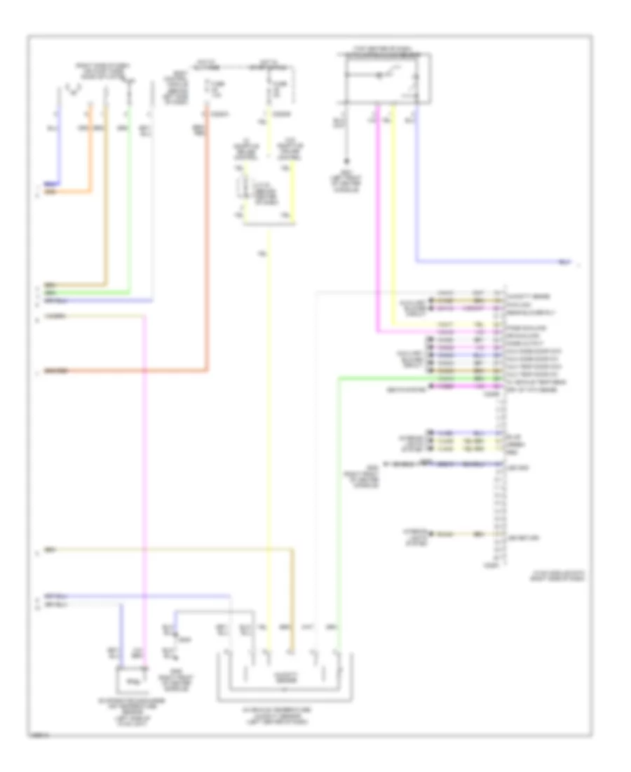
Automatic A/C Wiring Diagram (1 of 4) for Ford Flex SEL 2013
 https://portal-diagnostov.com/license.html
Automotive Electricians Portal FZCO
Automotive Electricians Portal FZCO
https://portal-diagnostov.com/license.html
https://portal-diagnostov.com/license.html
Automotive Electricians Portal FZCO
Automotive Electricians Portal FZCO
List of elements for Automatic A/C Wiring Diagram (1 of 4) for Ford Flex SEL 2013:
- (main wiring harness, near breakout to blower motor speed control) s210
- (main wiring harness, near breakout to c210)
- (on blower motor) blower motor speed control
- (right side of hvac unit) blower motor
- Aux mode dr fdbk
- Aux temp dr fdbk
- Auxiliary blower circuit
- Battery junction box (bjb) (left side of engine compt)
- Blower motor relay
- C210
- C213
- C228a
- C228b
- Ch123
- Ch207
- Ch208
- Ch212
- Ch213
- Ch228
- Ch229
- Ch238
- Ch239
- Cha35
- Cha36
- Cha37
- Chs11
- Chs12
- Computer data lines system
- Crd02
- Defogger system
- Defrost req
- Driv temp act fdbk
- Driv temp dr ccw
- Driv temp dr cw
- Driver temperature blend door actuator (left side of hvac unit)
- Drv heater feed
- Drv htd seat element
- Evap temp sens
- Fr blwr rly
- Fuse 20a (or 30a)
- Fuse 40a
- Fuse 5a
- G200 (right front of center console)
- G201 (left front of center console)
- Gd374
- Gnd
- Hot at all times
- Hot in start or run
- Hvac module datc (right side of dash)
- Lh111
- Mode 1 act fdbk
- Mode door actuator (left side of hvac unit)
- Mode dr 1 ccw
- Mode dr 1 cw
- Mot+
- Mot-
- Ms can +
- Ms can -
- Pass heater feed
- Pass htd seat element
- Pass st ntc sense
- Pass temp act fdbk rear ctrl blower output
- Pass temp door ccw
- Pass temp door cw
- Passenger temperature blend door actuator (right side of dash)
- Pwm
- Rear sig feed 1
- Rear sig feed 2
- Rear sig feed 3
- Rear temp input
- Recirc act fdbk
- Recirc ccw
- Recirc cw
- Return
- Rh111
- S200
- S208
- S209 (main wiring harness, near breakout to accessory protocol interface module)
- Sbb29
- Sbp46
- Seats system
- Var blwr ctrl
- Vbatt
- Vdb06
- Vdb07
- Vh101
- Vh406
- Vh436
- Vh438
- Vh440
- Vh441
- Vha09
- Vha18
- Vha19
- Vha39
- Vhs27
- Vref
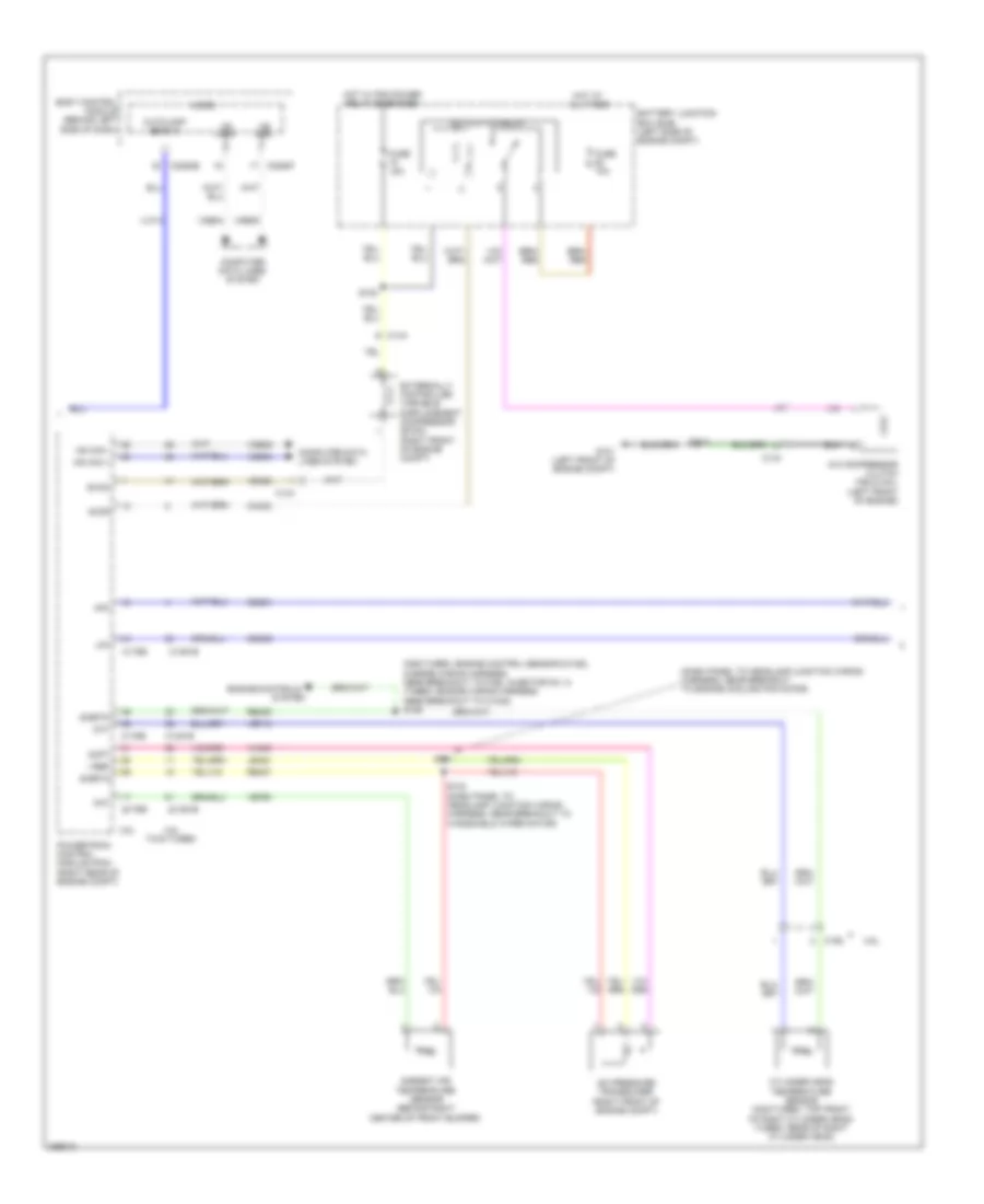
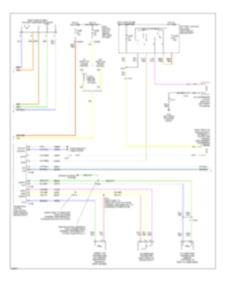
Automatic A/C Wiring Diagram (2 of 4) for Ford Flex SEL 2013
List of elements for Automatic A/C Wiring Diagram (2 of 4) for Ford Flex SEL 2013:
- (right side of dash) air inlet mode door actuator
- (top center of dash) autolamp/sunload sensor
- Aux mode door ccw
- Aux mode door cw
- Aux temp door ccw
- Aux temp door cw
- Auxiliary blower circuit
- Body control module (behind left side of dash)
- C2280a
- C2280b
- C228b
- C228c
- Ch112
- Ch242
- Ch243
- Ch244
- Ch245
- Dr sunload
- Drv st ntc sense
- Evaporator discharge air temperature sensor (left side of hvac unit)
- Fuse 10a
- Fuse 5a
- G200 (right front of center console)
- G201 (left front of center console)
- Gd215
- Green
- Hot at all times
- Hot in start or run
- Humidity sense
- Humidity sensor
- Hvac module datc (right side of dash)
- In vehicle temp sens
- In-vehicle temperature/ humidity sensor (left center of dash)
- Interior lights system
- J/c 24 (behind center of dash)
- Led gnd
- Led return
- Mode output
- Pass sunload
- Pwm com
- Rear blower rly
- Red
- Rln44
- S205
- Seats system
- Vh413
- Vh414
- Vh416
- Vh417
- Vha25
- Vha38
- Vhs26
- Vln48
- Vln49
- Vln50
- W/ adaptive cruise control
- W/o adaptive cruise control
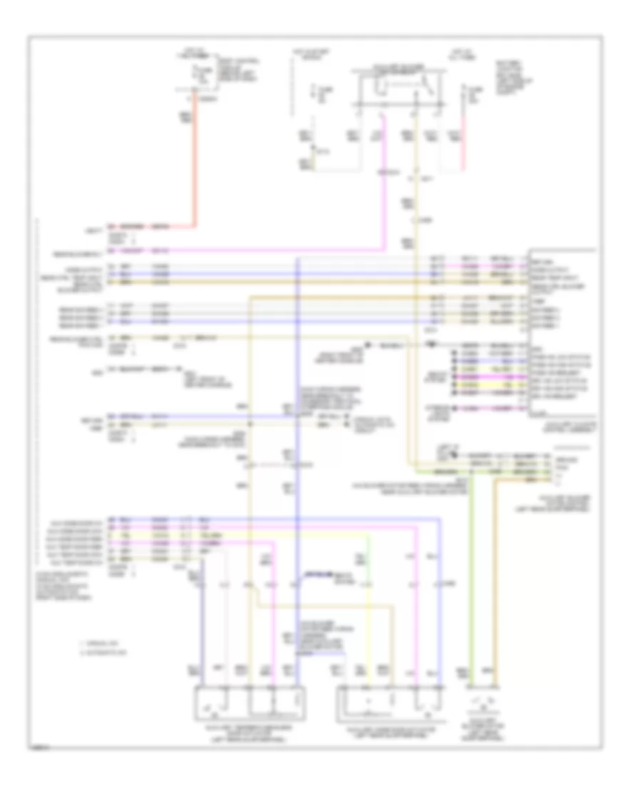
Automatic A/C Wiring Diagram (3 of 4) for Ford Flex SEL 2013
List of elements for Automatic A/C Wiring Diagram (3 of 4) for Ford Flex SEL 2013:
- (dash panel to headlamp junction wiring harness, near breakout to engine cooling fan motor)
- (non-turbo: engine control sensor & fuel charge wiring harness, near breakout to fuel injector no. 3) (turbo: engine wiring harness, near breakout to c1045) s126
- 3.5l
- 3.5l twin turbo
- A/c clutch relay
- A/c compressor clutch field coil (left front of engine)
- A/c pressure transducer (right front of engine compt)
- Aat
- Accr
- Acpt
- Ambient air temperature sensor (behind right center of front bumper)
- Autolamp sens in
- Battery junction box (bjb) (left side of engine compt)
- Body control module (behind left side of dash)
- C1381b
- C1381e
- C144
- C175b
- C175e
- C192
- C2280b
- C2280f
- Cec01
- Cec02
- Ch302
- Cht
- Computer data lines system
- Cylinder head temperature sensor (non-turbo: top front of right cylinder head) (turbo: rear of right cylinder head)
- Engine controls
- Evdc
- Externally controlled variable displacement compressor (evdc) (right front of engine compt)
- Fuse 10a
- Fuse 15a
- G101 (left front of engine compt)
- Hfc
- Hot at all times
- Hot w/ pcm power relay energized
- Hs can +
- Hs can -
- Hs can+
- Hs can-
- Le424
- Lfc
- Micro
- Powertrain control module (pcm) (right rear of engine compt)
- Re405
- Re407
- S101
- S108
- S114
- S133 (dash panel to headlamp junction wiring harness, near breakout to windshield wiper motor)
- Sigrtn
- System
- Vdb04
- Vdb05
- Ve462
- Ve712
- Ve750
- Vh433
- Vlf14
- Vref
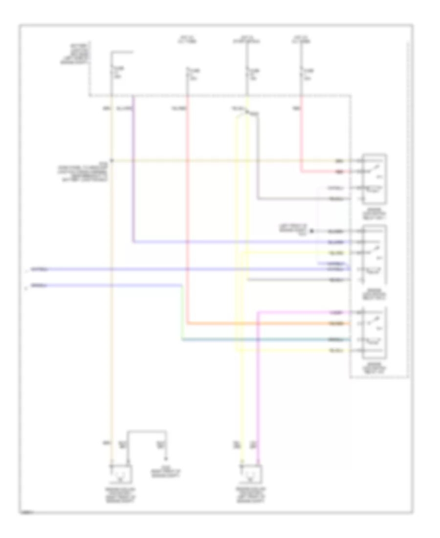
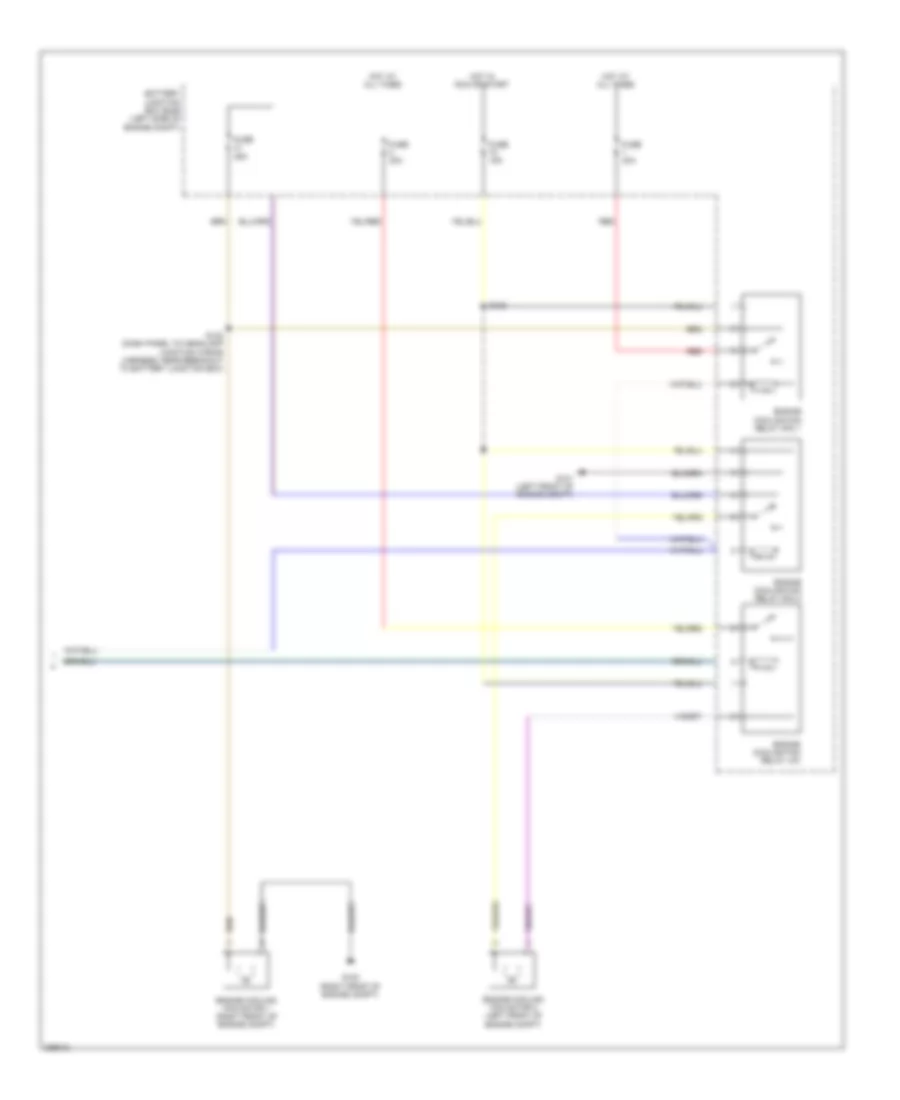
Automatic A/C Wiring Diagram (4 of 4) for Ford Flex SEL 2013
List of elements for Automatic A/C Wiring Diagram (4 of 4) for Ford Flex SEL 2013:
- (left front of engine compt) g101
- Battery junction box (bjb) (left side of engine compt)
- Engine cooling fan motor 1 (right front of engine compt)
- Engine cooling fan motor 2 (left front of engine compt)
- Engine cooling fan relay hfc 1
- Engine cooling fan relay hfc 2
- Engine cooling fan relay lfc
- Fuse 15a
- Fuse 25a
- Fuse 40a
- G100 (right front of engine compt)
- Hot at all times
- Hot in start or run
- Red
- S108
- S122 (dash panel to headlamp junction wiring harness, near breakout to battery junction box)
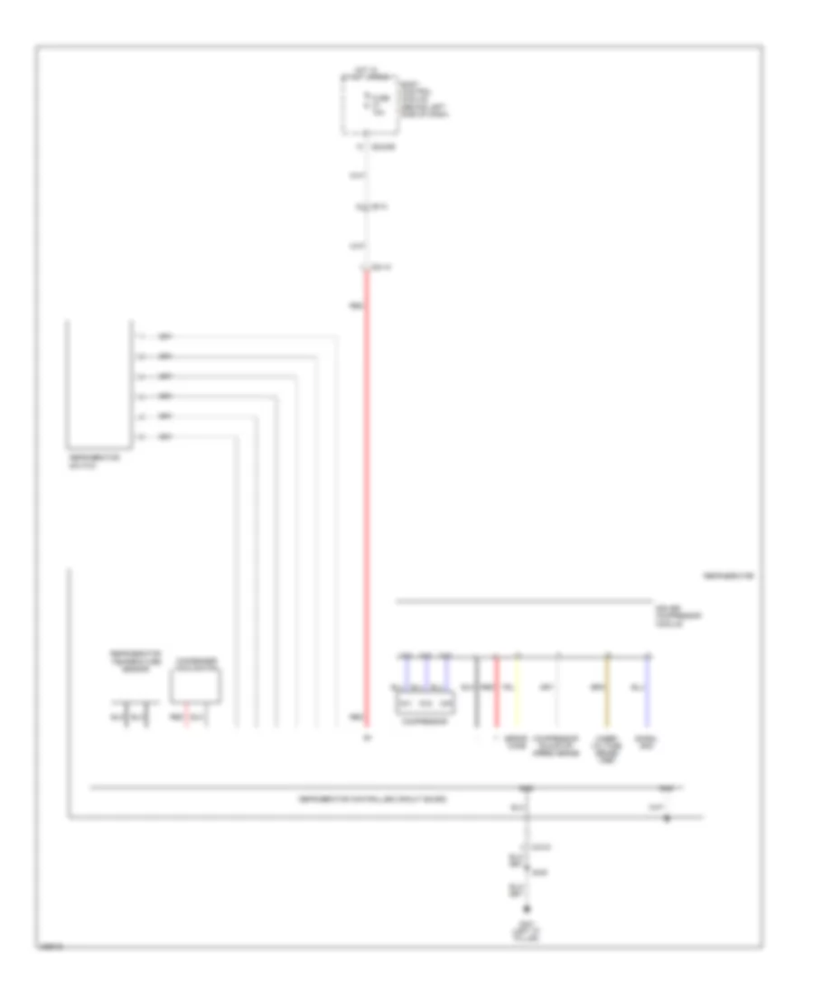
Auxiliary Blower Wiring Diagram for Ford Flex SEL 2013
List of elements for Auxiliary Blower Wiring Diagram for Ford Flex SEL 2013:
- (+)
- (-)
- (left "d" pillar) g401
- (main wiring harness, near breakout to accessory protocol interface module) s209
- Automatic a/c
- Aux mode door ccw
- Aux mode door cw
- Aux mode door fdbk
- Aux temp door ccw
- Aux temp door cw
- Aux temp door fdbk
- Auxiliary blower motor (left rear quarterpanel)
- Auxiliary blower motor control (left rear quarterpanel)
- Auxiliary blower motor relay
- Auxiliary climate control assembly
- Auxiliary mode door actuator (left rear quarterpanel)
- Auxiliary temperature blend door actuator (left rear quarterpanel)
- Battery junction box (bjb) (left side of of engine compt)
- Body control module (behind left side of dash)
- C210
- C211
- C214
- C215
- C2280a
- C228a
- C228b
- C2357a
- C2357b
- C465
- Ch112
- Ch242
- Ch243
- Ch244
- Ch245
- Cha35
- Cha36
- Cha37
- Chs47
- Chs48
- Chs49
- Chs51
- Chs52
- Chs53
- Drv hs high status
- Drv hs low status
- Drv hs request
- Fuse 10a
- Fuse 30a
- Fuse 5a
- G200 (right front of center console)
- G201 (left front of center console)
- Gd374
- Gd375
- Gnd
- Ground
- Hot at all times
- Hot in start or run
- Hvac module emtc (manual a/c) hvac module datc (automatic a/c) (right side of dash)
- Illum
- Interior lights system
- Lh111
- Manual a/c
- Manual a/c & automatic a/c circuit
- Mode output
- Near auxiliary blower motor) s410
- Pass hs high status
- Pass hs low status
- Pass hs request
- Pwm
- Rear blower ctrl pwm com c2357b
- Rear blower rly
- Rear ctrl blower output
- Rear ctrl temp input rear ctrl blower output
- Rear sig feed 1
- Rear sig feed 2
- Rear sig feed 3
- Rear temp input
- Return
- Rh111
- S112
- S208 (main wiring harness, near breakout to c210)
- S341
- S412 (a/c blower motor feed wiring harness, near auxiliary blower motor)
- Sbp46
- Seats system
- Sig feed 1
- Sig feed 2
- Sig feed 3
- Vbatt
- Vha09
- Vha18
- Vha19
- Vha25
- Vha38
- Vha39
- Vln04
- Vref
Cool Box Wiring Diagram for Ford Flex SEL 2013
List of elements for Cool Box Wiring Diagram for Ford Flex SEL 2013:
- Body control module (behind left side of dash)
- C215
- C2280b
- C3415
- Ch1
- Ch2
- Ch3
- Compressor
- Compressor run/stop speed sense
- Condenser cooling fan
- Driver compressor module
- Error code
- Fuse 10a
- G401 (left "d" pillar)
- Gnd
- Hot in start or run
- Red
- Refrigerator
- Refrigerator controller circuit board
- Refrigerator switch
- Refrigerator temperature sensor
- S420
- Signal gnd
- Under voltage sense vref
Manual A/C Wiring Diagram (1 of 3) for Ford Flex SEL 2013
List of elements for Manual A/C Wiring Diagram (1 of 3) for Ford Flex SEL 2013:
- (left side of hvac unit) evaporator discharge air temperature sensor
- (main wiring harness, near breakout to blower motor speed control)
- (main wiring harness, near breakout to c210)
- (on blower motor) blower motor speed control
- (right side of hvac unit) blower motor
- Aux mode door ccw
- Aux mode door cw
- Aux mode dr fdbk
- Aux temp door ccw
- Aux temp door cw
- Aux temp dr fdbk
- Auxiliary blower circuit
- Battery junction box (bjb) (left side of engine compt)
- Blower motor relay
- C210
- C2357a
- C2357b
- Ch112
- Ch123
- Ch207
- Ch208
- Ch228
- Ch229
- Ch238
- Ch239
- Ch242
- Ch243
- Ch244
- Ch245
- Cha35
- Cha36
- Cha37
- Computer data lines system
- Crd02
- Defogger system
- Defrost req
- Driv temp act fdbk
- Driv temp dr ccw
- Driv temp dr cw
- Driver temperature blend door actuator (left side of hvac unit)
- Evap temp sens
- Fr blwr rly
- Fuse 40a
- Fuse 5a
- G200 (right front of center console)
- G201 (left front of center console)
- Gd374
- Gnd
- Hot at all times
- Hot in run or start
- Humidity sense
- Humidity sensor
- Hvac module emtc (right side of dash)
- In veh temp sens
- In-vehicle temperature/humidity sensor (left center of dash)
- Lh111
- Mode 1 act fdbk
- Mode door actuator (left side of hvac unit)
- Mode dr 1 ccw
- Mode dr 1 cw
- Mode output
- Mot+
- Mot-
- Ms can +
- Ms can -
- Pwm
- Pwm com
- Rear blower rly
- Rear ctrl blower output
- Rear sig feed 1
- Rear sig feed 2
- Rear sig feed 3
- Rear temp input
- Recirc act fdbk
- Recirc ccw
- Recirc cw
- Return
- Rh111
- S205
- S208
- S209 (main wiring harness, near breakout to accessory protocol interface module)
- S210
- Sbp46
- Var blwr ctrl
- Vbatt
- Vdb06
- Vdb07
- Vh101
- Vh406
- Vh413
- Vh414
- Vh436
- Vh438
- Vh440
- Vha09
- Vha18
- Vha19
- Vha25
- Vha38
- Vha39
- Vref
Manual A/C Wiring Diagram (2 of 3) for Ford Flex SEL 2013
List of elements for Manual A/C Wiring Diagram (2 of 3) for Ford Flex SEL 2013:
- (dash panel to headlamp junction wiring harness, near breakout to engine cooling fan motor)
- (engine control sensor & fuel charge wiring harness, near breakout to fuel injector no. 3)
- (right front of engine compt) externally controlled variable displacement compressor (evdc)
- (right side of dash) air inlet mode door actuator
- A/c clutch relay
- A/c compressor clutch field coil (left front of engine)
- A/c pressure transducer (right front of engine compt)
- Aat
- Accr
- Acpt
- Ambient air temperature (aat) sensor (behind right center of front bumper)
- Battery junction box (bjb) (left side of engine compt)
- Body control module (behind left side of dash)
- C144
- C175b
- C175e
- C192
- C2280a
- C2280b
- Cec01
- Cec02
- Ch302
- Cht
- Compt)
- Computer data lines system
- Cylinder head temperature sensor (top front of right cylinder head)
- Engine controls system
- Evdc
- Fuse 10a
- Fuse 15a
- Fuse 5a
- G101 (left front of engine
- Hfc
- Hot at all times
- Hot in run or start
- Hot w/ pcm power relay energized
- Hs can +
- Hs can -
- J/c 24 (behind center of dash)
- Le424
- Lfc
- Powertrain control module (pcm) (right rear of engine compt)
- Re405
- Re407
- S101
- S108
- S114
- S126
- S133 (dash panel to headlamp junction wiring harness, near breakout to windshield wiper motor)
- Sigrtn
- Vdb04
- Vdb05
- Ve462
- Ve712
- Ve750
- Vh433
- Vref
- W/ adaptive cruise control
- W/o adaptive cruise control
Manual A/C Wiring Diagram (3 of 3) for Ford Flex SEL 2013
List of elements for Manual A/C Wiring Diagram (3 of 3) for Ford Flex SEL 2013:
- Battery junction box (bjb) (left side of engine compt)
- Engine cooling fan motor 1 (right front of engine compt)
- Engine cooling fan motor 2 (left front of engine compt)
- Engine cooling fan relay hfc 1
- Engine cooling fan relay hfc 2
- Engine cooling fan relay lfc
- Fuse 15a
- Fuse 25a
- Fuse 40a
- G100 (right front of engine compt)
- G101 (left front of engine compt)
- Hot at all times
- Hot in run or start
- Red
- S108
- S122 (dash panel to headlamp junction wiring harness, near breakout to battery junction box)

 Čeština
 Dansk
Dansk Deutsch
 Ελληνικά
 English
 Español
 Suomi
Suomi Français
 Français
 עברית
עברית Hrvatski
 Magyar
 Italiano
 日本語
日本語 한국어
한국어 Nederlands
 Polski
 Português
 Português
 Română
 Русский
 Slovenčina
 Slovenščina
 Svenska
 Türkçe
 中文 (中国)