ANTI-LOCK BRAKES
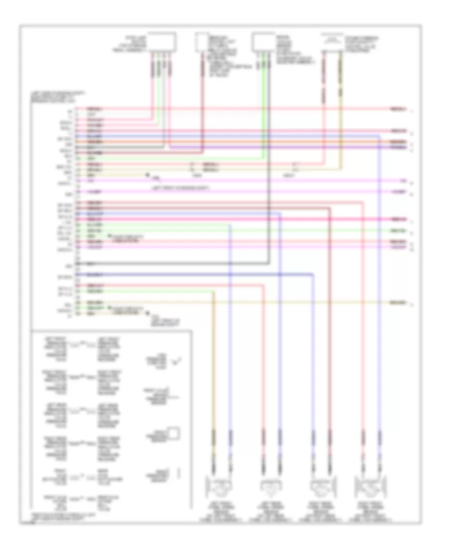
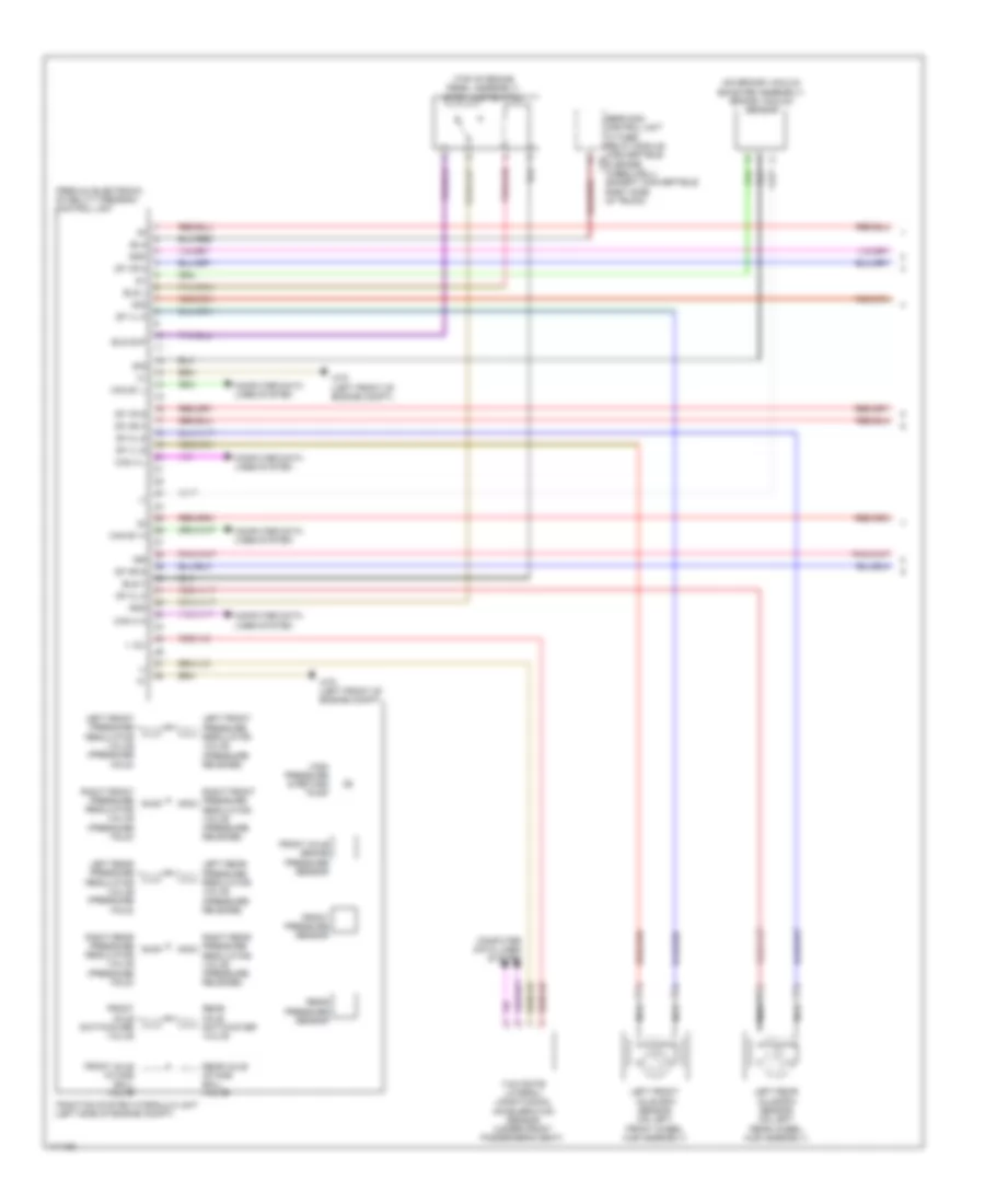
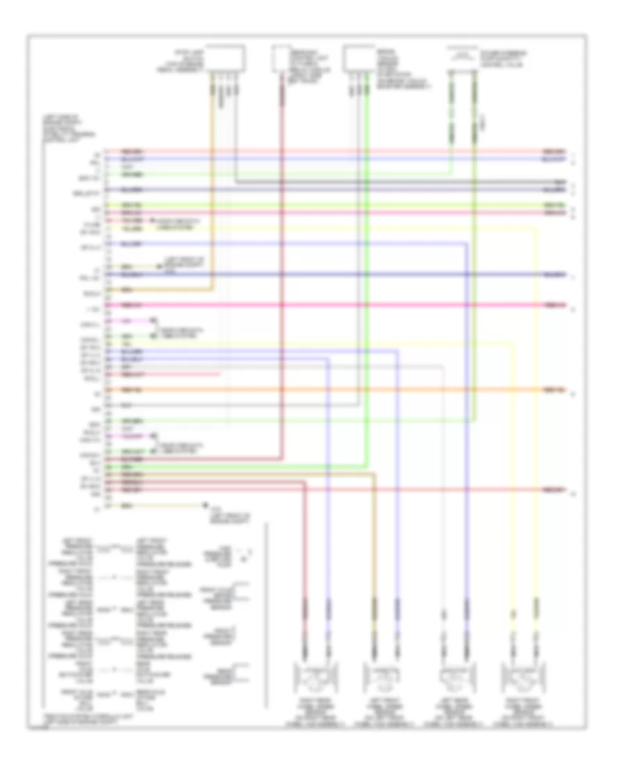
Anti-lock Brakes Wiring Diagram, Convertible with Basic (1 of 2) for Mercedes-Benz E350 2013

List of elements for Anti-lock Brakes Wiring Diagram, Convertible with Basic (1 of 2) for Mercedes-Benz E350 2013:
- (-)
- (left front of engine compt)
- (left side of engine compt) electronic stability program control unit
- + 12v
- 30g
- Bla
- Bls_h
- Bls_l
- Bls_m
- Brake vacuum sensor (w/ eco start/stop) (on brake vacuum booster assembly)
- Can d h
- Can d l
- Can e h
- Can e l
- Computer data lines system
- Df hl m
- Df hl s
- Df hr m
- Df hr s
- Df vl m
- Df vl s
- Df vr m
- Df vr s
- Eco
- Eco 12v
- Front axle brake pressure sensor
- Front axle intake ball valve
- Front axle switchover valve
- Front pressure sensor
- High pressure & return pump
- Left front pressure regulator valve (pressure hold)
- Left front pressure regulator valve (pressure release)
- Left front wheel speed sensor (on left front wheel hub assembly)
- Left rear pressure regulator valve (pressure hold)
- Left rear pressure regulator valve (pressure release)
- Left rear wheel speed sensor (on left rear wheel hub assembly)
- Nca
- Pml
- Pml 12v
- Power steering pump quantity control valve (if equipped)
- Rear axle intake ball valve
- Rear axle switchover valve
- Rear pressure sensor
- Rear sam control unit w/ fuse & relay module (convertible: c9i in spare wheelwell) (except convertible: right side of trunk)
- Right front pressure regulator valve (pressure hold)
- Right front pressure regulator valve (pressure release)
- Right front wheel speed sensor (on right front wheel hub assembly)
- Right rear pressure regulator valve (pressure hold)
- Right rear pressure regulator valve (pressure release)
- Right rear wheel speed sensor (on right rear wheel hub assembly)
- Sig
- Stop lamp switch (top of brake pedal assembly)
- Traction system hydraulic unit (left side of engine compt)
- W70
- W70 (left front of engine compt)
- X26-c1
- X35/6
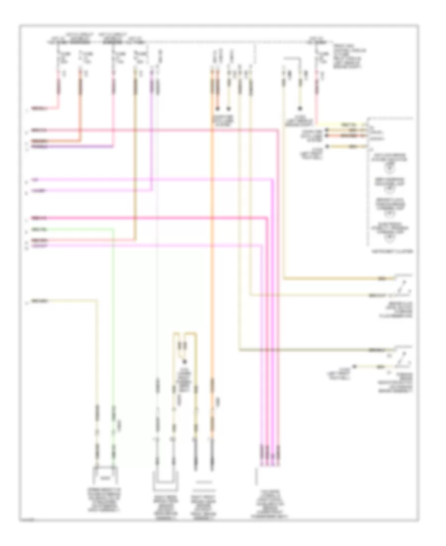
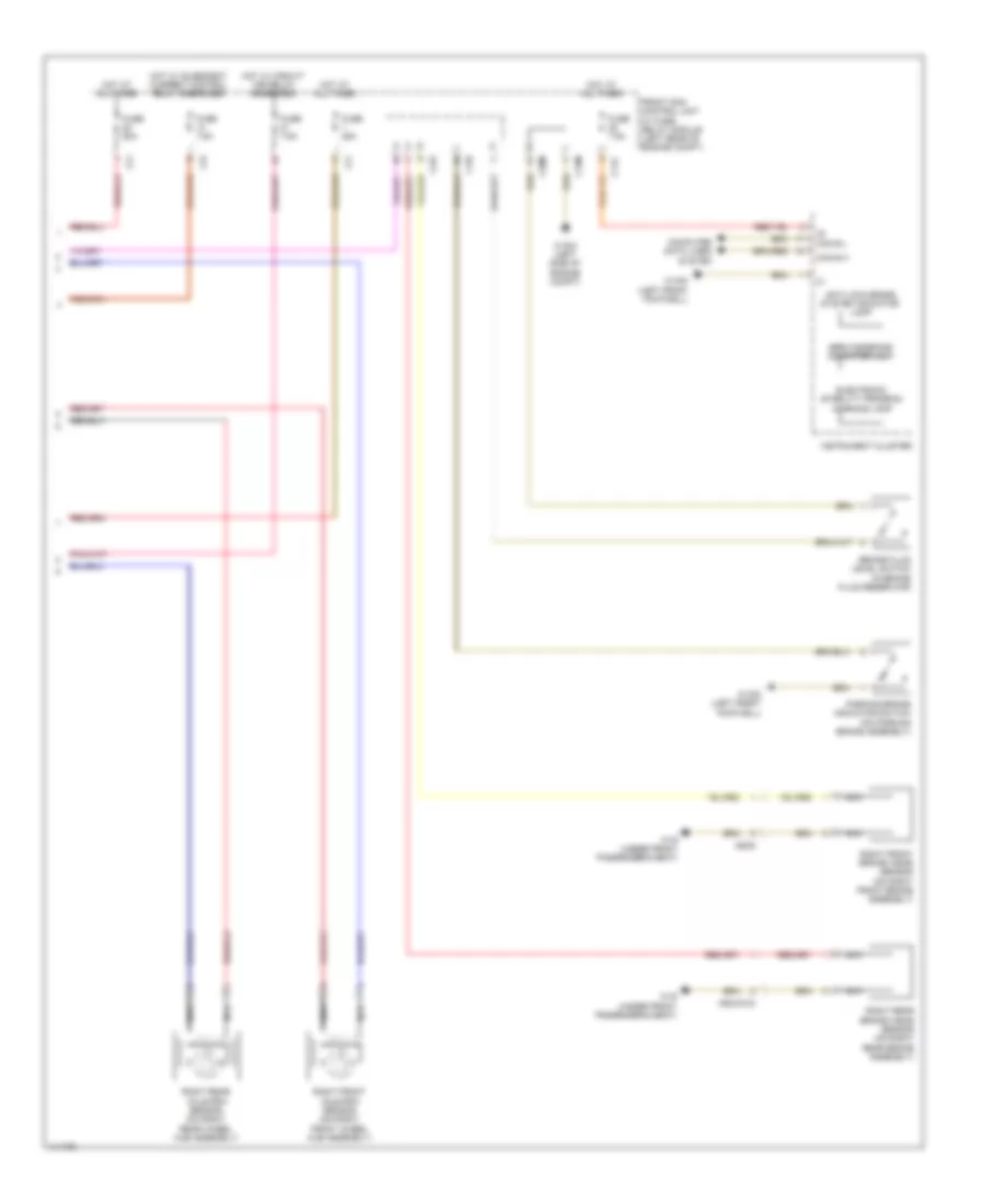
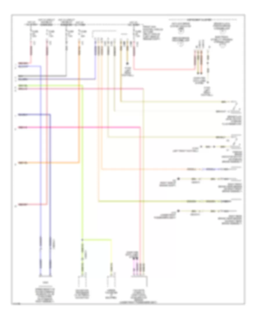
Anti-lock Brakes Wiring Diagram, Convertible with Basic (2 of 2) for Mercedes-Benz E350 2013
List of elements for Anti-lock Brakes Wiring Diagram, Convertible with Basic (2 of 2) for Mercedes-Benz E350 2013:
- Antilock brake system indicator lamp
- Bbv hr
- Bbv vl
- Brake fluid & parking brake warning lamp
- Brake fluid level switch (in brake fluid reservoir)
- C11c
- C15m
- C19i
- C20m
- C22i
- C2i
- C7i
- Can b h
- Can b l
- Computer data lines system
- Electronic stability program warning lamp
- Front sam control module w/ fuse/ relay module (left rear of engine compt)
- Fuse 25a
- Fuse 50a
- Fuse 7.5a
- Hot at all times
- Hot w/ circuit 15r relay energized
- Hot w/ circuit 30g relay energized
- Instrument cluster
- Nca
- Parking brake indicator switch (on parking brake assembly)
- Right front brake wear sensor (on right front brake assembly)
- Right rear brake wear sensor (on right rear brake assembly)
- Service brake indicator lamp
- Speed-sensitive power steering solenoid valve (if equipped) (on steering rack assembly)
- W15/5 (left front footwell)
- W16/5 (left rear of engine compt)
- W19 (under front passen- ger's seat)
- X18/33
- X62/33
- X62/6
- Yaw rate, lateral & longitudinal acceleration sensor (under front passenger's seat)
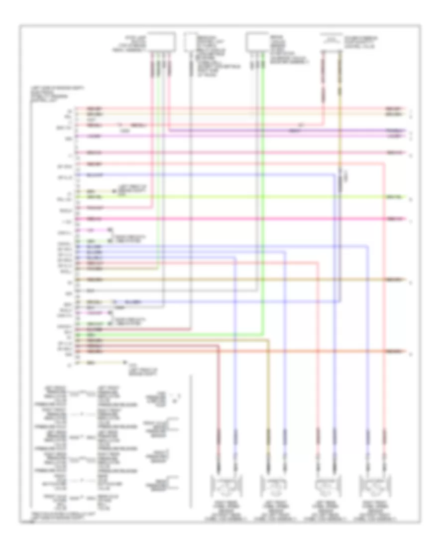
Anti-lock Brakes Wiring Diagram, Coupe with Basic (1 of 2) for Mercedes-Benz E350 2013
List of elements for Anti-lock Brakes Wiring Diagram, Coupe with Basic (1 of 2) for Mercedes-Benz E350 2013:
- (-)
- (left front of engine compt)
- (left side of engine compt) electronic stability program control unit
- + 12v
- 30g
- Bla
- Bls_h
- Bls_l
- Bls_m
- Brake vacuum sensor (w/ eco start/stop) (on brake vacuum booster assembly)
- Can d h
- Can d l
- Can e h
- Can e l
- Computer data lines system
- Df hl m
- Df hl s
- Df hr m
- Df hr s
- Df vl m
- Df vl s
- Df vr m
- Df vr s
- Eco
- Eco 12v
- Front axle brake pressure sensor
- Front axle intake ball valve
- Front axle switchover valve
- Front pressure sensor
- High pressure & return pump
- Left front pressure regulator valve (pressure hold)
- Left front pressure regulator valve (pressure release)
- Left front wheel speed sensor (on left front wheel hub assembly)
- Left rear pressure regulator valve (pressure hold)
- Left rear pressure regulator valve (pressure release)
- Left rear wheel speed sensor (on left rear wheel hub assembly)
- Nca
- Pml
- Pml 12v
- Power steering pump quantity control valve (if equipped)
- Rear axle intake ball valve
- Rear axle switchover valve
- Rear pressure sensor
- Rear sam control unit w/ fuse & relay module (convertible: c9i in spare wheelwell) (except convertible: right side of trunk)
- Right front pressure regulator valve (pressure hold)
- Right front pressure regulator valve (pressure release)
- Right front wheel speed sensor (on right front wheel hub assembly)
- Right rear pressure regulator valve (pressure hold)
- Right rear pressure regulator valve (pressure release)
- Right rear wheel speed sensor (on right rear wheel hub assembly)
- Sig
- Stop lamp switch (top of brake pedal assembly)
- Traction system hydraulic unit (left side of engine compt)
- W70
- W70 (left front of engine compt)
- X26-c1
- X35/6
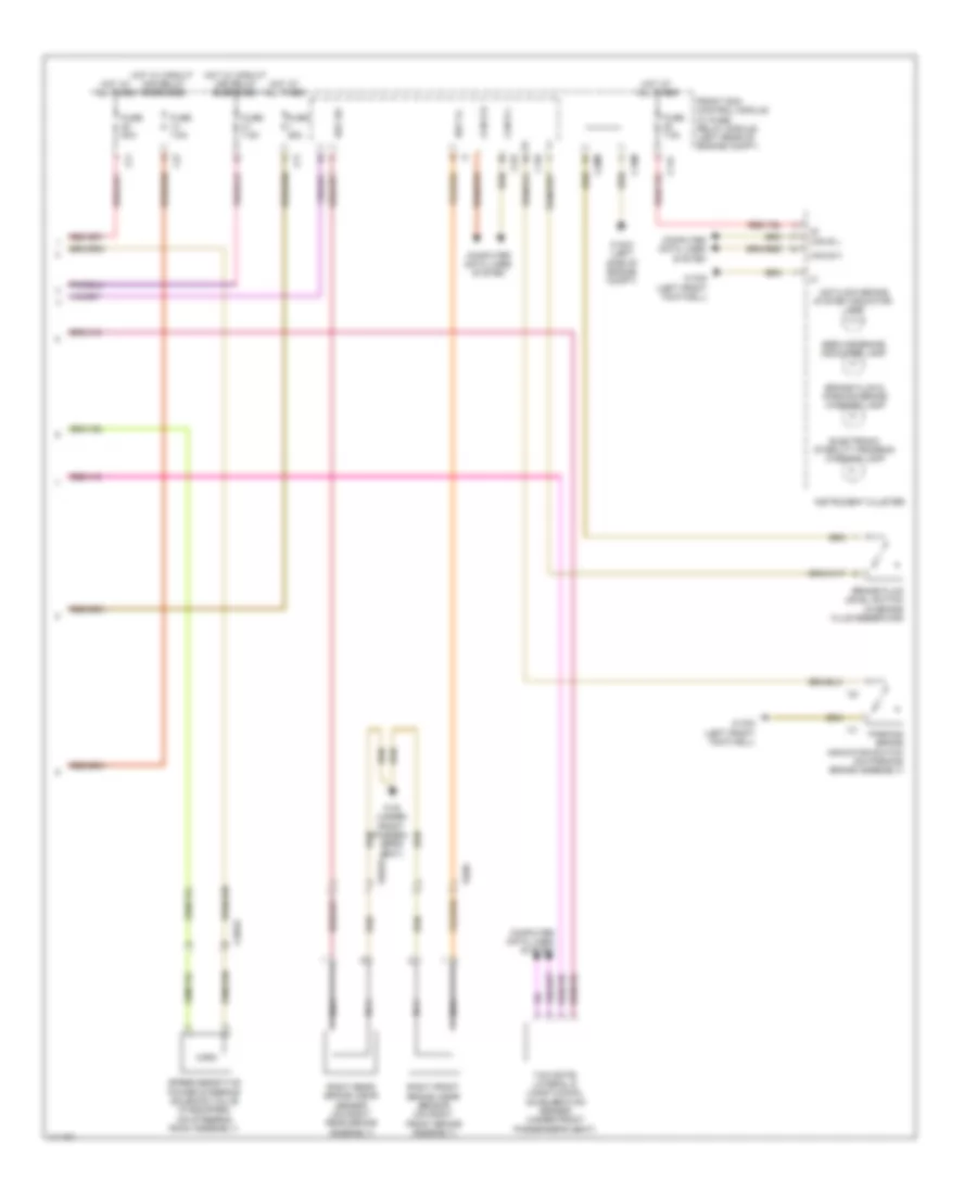
Anti-lock Brakes Wiring Diagram, Coupe with Basic (2 of 2) for Mercedes-Benz E350 2013
List of elements for Anti-lock Brakes Wiring Diagram, Coupe with Basic (2 of 2) for Mercedes-Benz E350 2013:
- Antilock brake system indicator lamp
- Bbv hr
- Bbv vl
- Brake fluid & parking brake warning lamp
- Brake fluid level switch (in brake fluid reservoir)
- C11c
- C15m
- C19i
- C20m
- C22i
- C2i
- C7i
- Can b h
- Can b l
- Computer data lines system
- Electronic stability program warning lamp
- Front sam control module w/ fuse/ relay module (left rear of engine compt)
- Fuse 25a
- Fuse 50a
- Fuse 7.5a
- Hot at all times
- Hot w/ circuit 15r relay energized
- Hot w/ circuit 30g relay energized
- Instrument cluster
- Nca
- Parking brake indicator switch (on parking brake assembly)
- Right front brake wear sensor (on right front brake assembly)
- Right rear brake wear sensor (on right rear brake assembly)
- Service brake indicator lamp
- Speed-sensitive power steering solenoid valve (if equipped) (on steering rack assembly)
- W15/5 (left front footwell)
- W16/5 (left rear of engine compt)
- W19 (under front passen- ger's seat)
- X18/33
- X62/33
- X62/6
- Yaw rate, lateral & longitudinal acceleration sensor (under front passenger's seat)
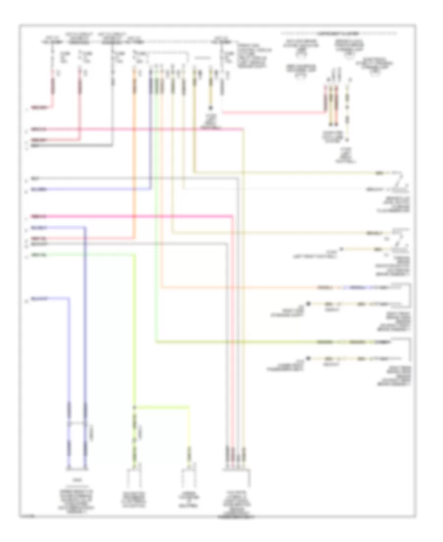
Anti-lock Brakes Wiring Diagram, Early Production Convertible with Premium (1 of 2) for Mercedes-Benz E350 2013
List of elements for Anti-lock Brakes Wiring Diagram, Early Production Convertible with Premium (1 of 2) for Mercedes-Benz E350 2013:
- (-)
- (left front of engine compt) w70
- (left side of engine compt) electronic stability program control unit
- + 12v
- 30g
- Bla
- Bls_h
- Bls_l
- Bls_m
- Brake vacuum sensor (w/ eco start/stop) (on brake vacuum booster assembly)
- Can e h
- Can e l
- Can h h
- Can h l
- Computer data lines system
- Df hl m
- Df hl s
- Df hr m
- Df hr s
- Df vl m
- Df vl s
- Df vr m
- Df vr s
- Eco
- Eco 12v
- Front axle brake pressure sensor
- Front axle intake ball valve
- Front axle switchover valve
- Front pressure sensor
- High pressure & return pump
- Left front pressure regulator valve (pressure hold)
- Left front pressure regulator valve (pressure release)
- Left front wheel speed sensor (on left front wheel hub assembly)
- Left rear pressure regulator valve (pressure hold)
- Left rear pressure regulator valve (pressure release)
- Left rear wheel speed sensor (on left rear wheel hub assembly)
- Nca
- Pml
- Pml 12v
- Power steering pump quantity control valve
- Rear axle intake ball valve
- Rear axle switchover valve
- Rear pressure sensor
- Rear sam control unit w/ fuse & relay module (convertible: c9i in spare wheelwell) (except convertible: right side of trunk)
- Right front pressure regulator valve (pressure hold)
- Right front pressure regulator valve (pressure release)
- Right front wheel speed sensor (on right front wheel hub assembly)
- Right rear pressure regulator valve (pressure hold)
- Right rear pressure regulator valve (pressure release)
- Right rear wheel speed sensor (on right rear wheel hub assembly)
- Sig
- Stop lamp switch (top of brake pedal assembly)
- Traction system hydraulic unit (left side of engine compt)
- W70 (left front of engine compt)
- X26-c1
- X35/6
Anti-lock Brakes Wiring Diagram, Early Production Convertible with Premium (2 of 2) for Mercedes-Benz E350 2013
List of elements for Anti-lock Brakes Wiring Diagram, Early Production Convertible with Premium (2 of 2) for Mercedes-Benz E350 2013:
- Antilock brake system indicator lamp
- Bbv hr
- Bbv vl
- Brake fluid & parking brake warning lamp
- Brake fluid level switch (in brake fluid reservoir)
- C11c
- C15m
- C19i
- C20m
- C22i
- C2i
- C7i
- Can b h
- Can b l
- Computer data lines system
- Electronic stability program warning lamp
- Front sam control module w/ fuse/ relay module (left rear of engine compt)
- Fuse 25a
- Fuse 50a
- Fuse 7.5a
- Hot at all times
- Hot w/ circuit 15r relay energized
- Hot w/ circuit 30g relay energized
- Instrument cluster
- Nca
- Parking brake indicator switch (on parking brake assembly)
- Right front brake wear sensor (on right front brake assembly)
- Right rear brake wear sensor (on right rear brake assembly)
- Service brake indicator lamp
- Speed-sensitive power steering solenoid valve (if equipped) (on steering rack assembly)
- W15/5 (left front footwell)
- W16/3 (left side of engine compt)
- W19 (under front passen- ger's seat)
- X18/33
- X62/33
- X62/6
- Yaw rate, lateral & longitudinal acceleration sensor (under front passenger's seat)
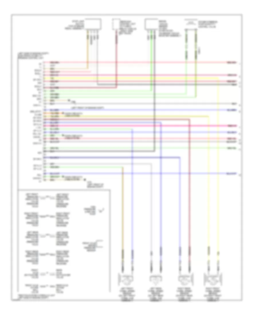
Anti-lock Brakes Wiring Diagram, Early Production Coupe with Premium (1 of 2) for Mercedes-Benz E350 2013
List of elements for Anti-lock Brakes Wiring Diagram, Early Production Coupe with Premium (1 of 2) for Mercedes-Benz E350 2013:
- (-)
- (left front of engine compt) w70
- (left side of engine compt) electronic stability program control unit
- + 12v
- 30g
- Bla
- Bls_h
- Bls_l
- Bls_m
- Brake vacuum sensor (w/ eco start/stop) (on brake vacuum booster assembly)
- Can e h
- Can e l
- Can h h
- Can h l
- Computer data lines system
- Df hl m
- Df hl s
- Df hr m
- Df hr s
- Df vl m
- Df vl s
- Df vr m
- Df vr s
- Eco
- Eco 12v
- Front axle brake pressure sensor
- Front axle intake ball valve
- Front axle switchover valve
- Front pressure sensor
- High pressure & return pump
- Left front pressure regulator valve (pressure hold)
- Left front pressure regulator valve (pressure release)
- Left front wheel speed sensor (on left front wheel hub assembly)
- Left rear pressure regulator valve (pressure hold)
- Left rear pressure regulator valve (pressure release)
- Left rear wheel speed sensor (on left rear wheel hub assembly)
- Nca
- Pml
- Pml 12v
- Power steering pump quantity control valve
- Rear axle intake ball valve
- Rear axle switchover valve
- Rear pressure sensor
- Rear sam control unit w/ fuse & relay module (convertible: c9i in spare wheelwell) (except convertible: right side of trunk)
- Right front pressure regulator valve (pressure hold)
- Right front pressure regulator valve (pressure release)
- Right front wheel speed sensor (on right front wheel hub assembly)
- Right rear pressure regulator valve (pressure hold)
- Right rear pressure regulator valve (pressure release)
- Right rear wheel speed sensor (on right rear wheel hub assembly)
- Sig
- Stop lamp switch (top of brake pedal assembly)
- Traction system hydraulic unit (left side of engine compt)
- W70 (left front of engine compt)
- X26-c1
- X35/6
Anti-lock Brakes Wiring Diagram, Early Production Coupe with Premium (2 of 2) for Mercedes-Benz E350 2013
List of elements for Anti-lock Brakes Wiring Diagram, Early Production Coupe with Premium (2 of 2) for Mercedes-Benz E350 2013:
- Antilock brake system indicator lamp
- Bbv hr
- Bbv vl
- Brake fluid & parking brake warning lamp
- Brake fluid level switch (in brake fluid reservoir)
- C11c
- C15m
- C19i
- C20m
- C22i
- C2i
- C7i
- Can b h
- Can b l
- Computer data lines system
- Electronic stability program warning lamp
- Front sam control module w/ fuse/ relay module (left rear of engine compt)
- Fuse 25a
- Fuse 50a
- Fuse 7.5a
- Hot at all times
- Hot w/ circuit 15r relay energized
- Hot w/ circuit 30g relay energized
- Instrument cluster
- Nca
- Parking brake indicator switch (on parking brake assembly)
- Right front brake wear sensor (on right front brake assembly)
- Right rear brake wear sensor (on right rear brake assembly)
- Service brake indicator lamp
- Speed-sensitive power steering solenoid valve (if equipped) (on steering rack assembly)
- W15/5 (left front footwell)
- W16/3 (left side of engine compt)
- W19 (under front passen- ger's seat)
- X18/33
- X62/33
- X62/6
- Yaw rate, lateral & longitudinal acceleration sensor (under front passenger's seat)
Anti-lock Brakes Wiring Diagram, Late Production Convertible with Premium (1 of 2) for Mercedes-Benz E350 2013
List of elements for Anti-lock Brakes Wiring Diagram, Late Production Convertible with Premium (1 of 2) for Mercedes-Benz E350 2013:
- (-)
- (on brake vacuum booster assembly) brake vacuum sensor
- (top of brake pedal assembly) stop lamp switch
- + 12v
- 15r
- 30g
- Bla
- Bls h
- Bls l
- Bls sup
- Can e1 h
- Can e1 l
- Can h h
- Can h l
- Computer data lines system
- Df hl m
- Df hl s
- Df hr m
- Df hr s
- Df vl m
- Df vl s
- Df vr m
- Df vr s
- Front axle brake pressure sensor
- Front axle intake ball valve
- Front axle switchover valve
- Front pressure sensor
- Gnd
- High pressure & return pump
- Left front axle rpm sensor (on left front wheel hub assembly)
- Left front pressure regulator valve (pressure hold)
- Left front pressure regulator valve (pressure release)
- Left rear axle rpm sensor (on left rear wheel hub assembly)
- Left rear pressure regulator valve (pressure hold)
- Left rear pressure regulator valve (pressure release)
- Nca
- Premium electronic stability program control unit
- Rear axle intake ball valve
- Rear axle switchover valve
- Rear pressure sensor
- Rear sam control unit w/ fuse/ relay module (convertible: c9i in spare wheelwell) (except convertible: right side of trunk)
- Right front pressure regulator valve (pressure hold)
- Right front pressure regulator valve (pressure release)
- Right rear pressure regulator valve (pressure hold)
- Right rear pressure regulator valve (pressure release)
- Sig
- Ssk
- Traction system hydraulic unit (left side of engine compt)
- W70 (left front of engine compt)
- Yaw rate/ lateral/ longitudinal acceleration sensor (under front passenger's seat)
Anti-lock Brakes Wiring Diagram, Late Production Convertible with Premium (2 of 2) for Mercedes-Benz E350 2013
List of elements for Anti-lock Brakes Wiring Diagram, Late Production Convertible with Premium (2 of 2) for Mercedes-Benz E350 2013:
- Anti-lock brake system indicator lamp
- Brake fluid level switch (in brake fluid reservoir)
- C11c
- C15m
- C19i
- C20m
- C22i
- C2i
- C7i
- Can b h
- Can b l
- Computer data lines system
- Electronic stability program warning lamp
- Front sam control unit w/ fuse/ relay module (left rear of engine compt)
- Fuse 25a
- Fuse 50a
- Fuse 7.5a
- Hot at all times
- Hot w/ circuit 15r relay energized
- Hot w/ quiescent current control relay energized
- Instrument cluster
- Nca
- Parking brake indicator switch (on parking brake assembly)
- Right front axle rpm sensor (on right front wheel hub assembly)
- Right front brake wear sensor (on right front brake assembly)
- Right rear axle rpm sensor (on right rear wheel hub assembly)
- Right rear brake wear sensor (on right rear brake assembly)
- Service brake indicator lamp
- W15/5 (left front footwell)
- W16/3 (left side of engine compt)
- W19 (under front passenger's seat)
- X62/33-c3
- X62/6
Anti-lock Brakes Wiring Diagram, Late Production Coupe with Premium (1 of 2) for Mercedes-Benz E350 2013
List of elements for Anti-lock Brakes Wiring Diagram, Late Production Coupe with Premium (1 of 2) for Mercedes-Benz E350 2013:
- (-)
- (on brake vacuum booster assembly) brake vacuum sensor
- (top of brake pedal assembly) stop lamp switch
- + 12v
- 15r
- 30g
- Bla
- Bls h
- Bls l
- Bls sup
- Can e1 h
- Can e1 l
- Can h h
- Can h l
- Computer data lines system
- Df hl m
- Df hl s
- Df hr m
- Df hr s
- Df vl m
- Df vl s
- Df vr m
- Df vr s
- Front axle brake pressure sensor
- Front axle intake ball valve
- Front axle switchover valve
- Front pressure sensor
- Gnd
- High pressure & return pump
- Left front axle rpm sensor (on left front wheel hub assembly)
- Left front pressure regulator valve (pressure hold)
- Left front pressure regulator valve (pressure release)
- Left rear axle rpm sensor (on left rear wheel hub assembly)
- Left rear pressure regulator valve (pressure hold)
- Left rear pressure regulator valve (pressure release)
- Nca
- Premium electronic stability program control unit
- Rear axle intake ball valve
- Rear axle switchover valve
- Rear pressure sensor
- Rear sam control unit w/ fuse/ relay module (convertible: c9i in spare wheelwell) (except convertible: right side of trunk)
- Right front pressure regulator valve (pressure hold)
- Right front pressure regulator valve (pressure release)
- Right rear pressure regulator valve (pressure hold)
- Right rear pressure regulator valve (pressure release)
- Sig
- Ssk
- Traction system hydraulic unit (left side of engine compt)
- W70 (left front of engine compt)
- Yaw rate/ lateral/ longitudinal acceleration sensor (under front passenger's seat)
Anti-lock Brakes Wiring Diagram, Late Production Coupe with Premium (2 of 2) for Mercedes-Benz E350 2013
List of elements for Anti-lock Brakes Wiring Diagram, Late Production Coupe with Premium (2 of 2) for Mercedes-Benz E350 2013:
- Anti-lock brake system indicator lamp
- Brake fluid level switch (in brake fluid reservoir)
- C11c
- C15m
- C19i
- C20m
- C22i
- C2i
- C7i
- Can b h
- Can b l
- Computer data lines system
- Electronic stability program warning lamp
- Front sam control unit w/ fuse/ relay module (left rear of engine compt)
- Fuse 25a
- Fuse 50a
- Fuse 7.5a
- Hot at all times
- Hot w/ circuit 15r relay energized
- Hot w/ quiescent current control relay energized
- Instrument cluster
- Nca
- Parking brake indicator switch (on parking brake assembly)
- Right front axle rpm sensor (on right front wheel hub assembly)
- Right front brake wear sensor (on right front brake assembly)
- Right rear axle rpm sensor (on right rear wheel hub assembly)
- Right rear brake wear sensor (on right rear brake assembly)
- Service brake indicator lamp
- W15/5 (left front footwell)
- W16/3 (left side of engine compt)
- W19 (under front passenger's seat)
- X62/33-c3
- X62/6
Anti-lock Brakes Wiring Diagram, Sedan with Basic (1 of 2) for Mercedes-Benz E350 2013
List of elements for Anti-lock Brakes Wiring Diagram, Sedan with Basic (1 of 2) for Mercedes-Benz E350 2013:
- (-)
- (left front of engine compt)
- (left side of engine compt) electronic stability program control unit
- + 12v
- 30g
- Bla
- Bls_h
- Bls_l
- Bls_m
- Brake vacuum sensor (w/ eco start/stop) (on brake vacuum booster assembly)
- Can e h
- Can e l
- Can h h
- Can h l
- Computer data lines system
- Df hl m
- Df hl s
- Df hr m
- Df hr s
- Df vl m
- Df vl s
- Df vr m
- Df vr s
- Eco
- Eco 12v
- Front axle brake pressure sensor
- Front axle intake ball valve
- Front axle switchover valve
- High pressure & return pump
- K-line
- Left front pressure regulator valve (pressure hold)
- Left front pressure regulator valve (pressure release)
- Left front wheel speed sensor (on left front wheel hub assembly)
- Left rear pressure regulator valve (pressure hold)
- Left rear pressure regulator valve (pressure release)
- Left rear wheel speed sensor (on left rear wheel hub assembly)
- Nca
- Pml
- Pml 12v
- Power steering pump quantity control valve
- Rear axle intake ball valve
- Rear axle switchover valve
- Rear sam control unit w/ fuse & relay module (right side c9i of trunk)
- Right front pressure regulator valve (pressure hold)
- Right front pressure regulator valve (pressure release)
- Right front wheel speed sensor (on right front wheel hub assembly)
- Right rear pressure regulator valve (pressure hold)
- Right rear pressure regulator valve (pressure release)
- Right rear wheel speed sensor (on right rear wheel hub assembly)
- Sig
- Ssk_stat
- Stop lamp switch (top of brake pedal assembly)
- Traction system hydraulic unit (left side of engine compt)
- W70
- W70 (left front of engine compt)
- X26-c1
Anti-lock Brakes Wiring Diagram, Sedan with Basic (2 of 2) for Mercedes-Benz E350 2013
List of elements for Anti-lock Brakes Wiring Diagram, Sedan with Basic (2 of 2) for Mercedes-Benz E350 2013:
- Antilock brake system indicator lamp
- Brake fluid & parking brake warning lamp
- Brake fluid level switch (in brake fluid reservoir)
- C11c
- C15m
- C19i
- C20m
- C22i
- C2i
- C7i
- Can b h
- Can b l
- Computer data lines system
- Electronic stability program warning lamp
- Front sam control module w/ fuse/ relay module (left rear of engine compt)
- Fuse 25a
- Fuse 40a
- Fuse 7.5a
- Hot at all times
- Hot w/ circuit 15r relay energized
- Hot w/ circuit 30g relay energized
- Instrument cluster
- Mirror taximeter (if equipped)
- Navigation processor (w/ external navigation)
- Nca
- Parking brake indicator switch (on parking brake assembly)
- Right front brake wear sensor (on right front brake assembly)
- Right rear brake wear sensor (on right rear brake assembly)
- Service brake indicator lamp
- Speed-sensitive power steering solenoid valve (if equipped) (on steering rack assembly)
- W15/2 (left front footwell)
- W15/5 (left front footwell)
- W19 (under front passenger's seat)
- W2 (right side of engine compt)
- X1/55-c1
- X18/33-c1
- X62/33-c1
- X62/6-c1
- Yaw rate, lateral & longitudinal acceleration sensor (under front passenger's seat)
Anti-lock Brakes Wiring Diagram, Sedan with Premium (1 of 2) for Mercedes-Benz E350 2013
List of elements for Anti-lock Brakes Wiring Diagram, Sedan with Premium (1 of 2) for Mercedes-Benz E350 2013:
- (-)
- (left front of engine compt) w70
- (left side of engine compt) electronic stability program control unit
- + 12v
- 30g
- Bla
- Bls_h
- Bls_l
- Bls_m
- Brake vacuum sensor (w/ eco start/stop) (on brake vacuum booster assembly)
- Can e h
- Can e l
- Can h h
- Can h l
- Computer data lines system
- Df hl m
- Df hl s
- Df hr m
- Df hr s
- Df vl m
- Df vl s
- Df vr m
- Df vr s
- Eco
- Eco 12v
- Front axle brake pressure sensor
- Front axle intake ball valve
- Front axle switchover valve
- Front pressure sensor
- High pressure & return pump
- K-line
- Left front pressure regulator valve (pressure hold)
- Left front pressure regulator valve (pressure release)
- Left front wheel speed sensor (on left front wheel hub assembly)
- Left rear pressure regulator valve (pressure hold)
- Left rear pressure regulator valve (pressure release)
- Left rear wheel speed sensor (on left rear wheel hub assembly)
- Nca
- Pml
- Pml 12v
- Power steering pump quantity control valve
- Rear axle intake ball valve
- Rear axle switchover valve
- Rear pressure sensor
- Rear sam control unit w/ fuse & relay module (right side c9i of trunk)
- Right front pressure regulator valve (pressure hold)
- Right front pressure regulator valve (pressure release)
- Right front wheel speed sensor (on right front wheel hub assembly)
- Right rear pressure regulator valve (pressure hold)
- Right rear pressure regulator valve (pressure release)
- Right rear wheel speed sensor (on right rear wheel hub assembly)
- Sig
- Ssk_stat
- Stop lamp switch (top of brake pedal assembly)
- Traction system hydraulic unit (left side of engine compt)
- W70 (left front of engine compt)
- X26-c1
Anti-lock Brakes Wiring Diagram, Sedan with Premium (2 of 2) for Mercedes-Benz E350 2013
List of elements for Anti-lock Brakes Wiring Diagram, Sedan with Premium (2 of 2) for Mercedes-Benz E350 2013:
- Antilock brake system indicator lamp
- Brake fluid & parking brake warning lamp
- Brake fluid level switch (in brake fluid reservoir)
- C11c
- C15m
- C19i
- C20m
- C22i
- C2i
- C7i
- Can b h
- Can b l
- Computer data lines system
- Electronic stability program warning lamp
- Front sam control module w/ fuse/ relay module (left rear of engine compt)
- Fuse 25a
- Fuse 40a
- Fuse 7.5a
- Hot at all times
- Hot w/ circuit 15r relay energized
- Hot w/ circuit 30g relay energized
- Instrument cluster
- Mirror taximeter (if equipped)
- Navigation processor (w/ external navigation)
- Nca
- Parking brake indicator switch (on parking brake assembly)
- Right front brake wear sensor (on right front brake assembly)
- Right rear brake wear sensor (on right rear brake assembly)
- Service brake indicator lamp
- Speed-sensitive power steering solenoid valve (if equipped) (on steering rack assembly)
- W15/2 (left front footwell)
- W15/5 (left front footwell)
- W19 (under front passenger's seat)
- W2 (right side of engine compt)
- X1/55-c1
- X18/33-c1
- X62/33-c1
- X62/6-c1
- Yaw rate, lateral & longitudinal acceleration sensor (under front passenger's seat)
Anti-lock Brakes Wiring Diagram, Wagon with Basic (1 of 2) for Mercedes-Benz E350 2013
List of elements for Anti-lock Brakes Wiring Diagram, Wagon with Basic (1 of 2) for Mercedes-Benz E350 2013:
- (-)
- (left front of engine compt)
- (left side of engine compt) electronic stability program control unit
- + 12v
- 30g
- Bla
- Bls_h
- Bls_l
- Bls_m
- Brake vacuum sensor (w/ eco start/stop) (on brake vacuum booster assembly)
- Can e h
- Can e l
- Can h h
- Can h l
- Computer data lines system
- Df hl m
- Df hl s
- Df hr m
- Df hr s
- Df vl m
- Df vl s
- Df vr m
- Df vr s
- Eco
- Eco 12v
- Front axle brake pressure sensor
- Front axle intake ball valve
- Front axle switchover valve
- High pressure & return pump
- K-line
- Left front pressure regulator valve (pressure hold)
- Left front pressure regulator valve (pressure release)
- Left front wheel speed sensor (on left front wheel hub assembly)
- Left rear pressure regulator valve (pressure hold)
- Left rear pressure regulator valve (pressure release)
- Left rear wheel speed sensor (on left rear wheel hub assembly)
- Nca
- Pml
- Pml 12v
- Power steering pump quantity control valve
- Rear axle intake ball valve
- Rear axle switchover valve
- Rear sam control unit w/ fuse & relay module (right side c9i of trunk)
- Right front pressure regulator valve (pressure hold)
- Right front pressure regulator valve (pressure release)
- Right front wheel speed sensor (on right front wheel hub assembly)
- Right rear pressure regulator valve (pressure hold)
- Right rear pressure regulator valve (pressure release)
- Right rear wheel speed sensor (on right rear wheel hub assembly)
- Sig
- Ssk_stat
- Stop lamp switch (top of brake pedal assembly)
- Traction system hydraulic unit (left side of engine compt)
- W70
- W70 (left front of engine compt)
- X26-c1
Anti-lock Brakes Wiring Diagram, Wagon with Basic (2 of 2) for Mercedes-Benz E350 2013
List of elements for Anti-lock Brakes Wiring Diagram, Wagon with Basic (2 of 2) for Mercedes-Benz E350 2013:
- Antilock brake system indicator lamp
- Brake fluid & parking brake warning lamp
- Brake fluid level switch (in brake fluid reservoir)
- C11c
- C15m
- C19i
- C20m
- C22i
- C2i
- C7i
- Can b h
- Can b l
- Computer data lines system
- Electronic stability program warning lamp
- Front sam control module w/ fuse/ relay module (left rear of engine compt)
- Fuse 25a
- Fuse 40a
- Fuse 7.5a
- Hot at all times
- Hot w/ circuit 15r relay energized
- Hot w/ circuit 30g relay energized
- Instrument cluster
- Mirror taximeter (if equipped)
- Navigation processor (w/ external navigation)
- Nca
- Parking brake indicator switch (on parking brake assembly)
- Right front brake wear sensor (on right front brake assembly)
- Right rear brake wear sensor (on right rear brake assembly)
- Service brake indicator lamp
- Speed-sensitive power steering solenoid valve (if equipped) (on steering rack assembly)
- W15/2 (left front footwell)
- W15/5 (left front footwell)
- W19 (under front passenger's seat)
- W2 (right side of engine compt)
- X1/55-c1
- X18/33-c1
- X62/33-c1
- X62/6-c1
- Yaw rate, lateral & longitudinal acceleration sensor (under front passenger's seat)
Anti-lock Brakes Wiring Diagram, Wagon with Premium (1 of 2) for Mercedes-Benz E350 2013
List of elements for Anti-lock Brakes Wiring Diagram, Wagon with Premium (1 of 2) for Mercedes-Benz E350 2013:
- (-)
- (left front of engine compt) w70
- (left side of engine compt) electronic stability program control unit
- + 12v
- 30g
- Bla
- Bls_h
- Bls_l
- Bls_m
- Brake vacuum sensor (w/ eco start/stop) (on brake vacuum booster assembly)
- Can e h
- Can e l
- Can h h
- Can h l
- Computer data lines system
- Df hl m
- Df hl s
- Df hr m
- Df hr s
- Df vl m
- Df vl s
- Df vr m
- Df vr s
- Eco
- Eco 12v
- Front axle brake pressure sensor
- Front axle intake ball valve
- Front axle switchover valve
- Front pressure sensor
- High pressure & return pump
- K-line
- Left front pressure regulator valve (pressure hold)
- Left front pressure regulator valve (pressure release)
- Left front wheel speed sensor (on left front wheel hub assembly)
- Left rear pressure regulator valve (pressure hold)
- Left rear pressure regulator valve (pressure release)
- Left rear wheel speed sensor (on left rear wheel hub assembly)
- Nca
- Pml
- Pml 12v
- Power steering pump quantity control valve
- Rear axle intake ball valve
- Rear axle switchover valve
- Rear pressure sensor
- Rear sam control unit w/ fuse & relay module (right side c9i of trunk)
- Right front pressure regulator valve (pressure hold)
- Right front pressure regulator valve (pressure release)
- Right front wheel speed sensor (on right front wheel hub assembly)
- Right rear pressure regulator valve (pressure hold)
- Right rear pressure regulator valve (pressure release)
- Right rear wheel speed sensor (on right rear wheel hub assembly)
- Sig
- Ssk_stat
- Stop lamp switch (top of brake pedal assembly)
- Traction system hydraulic unit (left side of engine compt)
- W70 (left front of engine compt)
- X26-c1
Anti-lock Brakes Wiring Diagram, Wagon with Premium (2 of 2) for Mercedes-Benz E350 2013
List of elements for Anti-lock Brakes Wiring Diagram, Wagon with Premium (2 of 2) for Mercedes-Benz E350 2013:
- Antilock brake system indicator lamp
- Brake fluid & parking brake warning lamp
- Brake fluid level switch (in brake fluid reservoir)
- C11c
- C15m
- C19i
- C20m
- C22i
- C2i
- C7i
- Can b h
- Can b l
- Computer data lines system
- Electronic stability program warning lamp
- Front sam control module w/ fuse/ relay module (left rear of engine compt)
- Fuse 25a
- Fuse 40a
- Fuse 7.5a
- Hot at all times
- Hot w/ circuit 15r relay energized
- Hot w/ circuit 30g relay energized
- Instrument cluster
- Mirror taximeter (if equipped)
- Navigation processor (w/ external navigation)
- Nca
- Parking brake indicator switch (on parking brake assembly)
- Right front brake wear sensor (on right front brake assembly)
- Right rear brake wear sensor (on right rear brake assembly)
- Service brake indicator lamp
- Speed-sensitive power steering solenoid valve (if equipped) (on steering rack assembly)
- W15/2 (left front footwell)
- W15/5 (left front footwell)
- W19 (under front passenger's seat)
- W2 (right side of engine compt)
- X1/55-c1
- X18/33-c1
- X62/33-c1
- X62/6-c1
- Yaw rate, lateral & longitudinal acceleration sensor (under front passenger's seat)