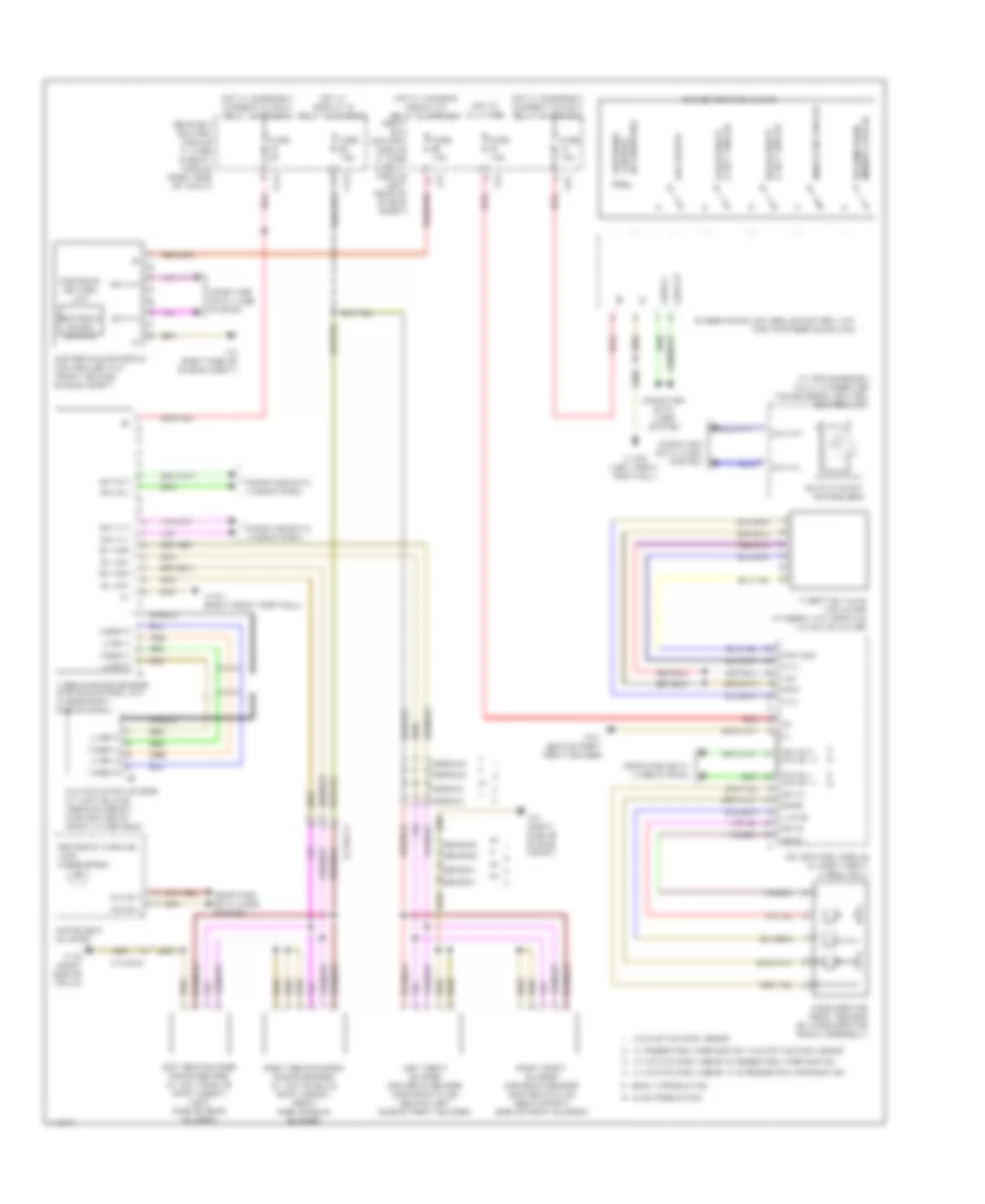
CRUISE CONTROL
3.0L TURBO DIESEL
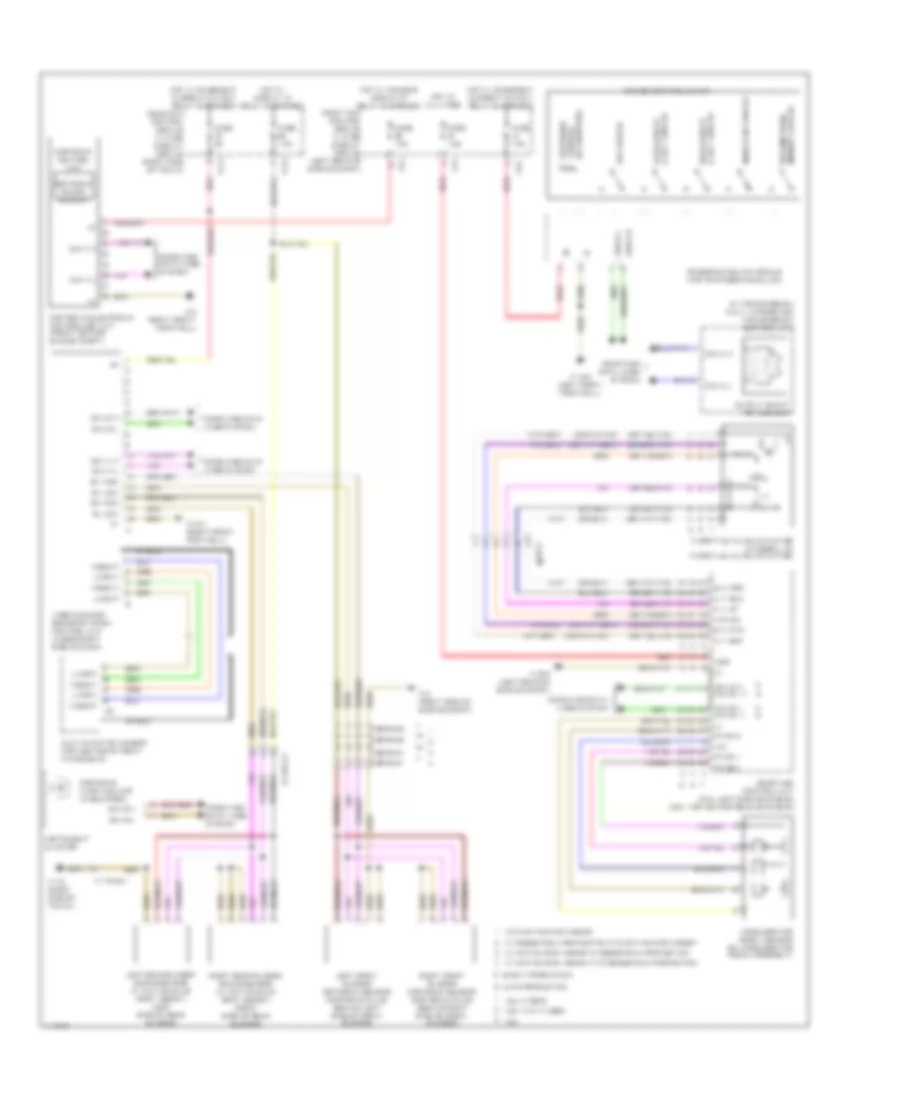
3.0L Turbo Diesel, Cruise Control Wiring Diagram for Mercedes-Benz E350 2013

List of elements for 3.0L Turbo Diesel, Cruise Control Wiring Diagram for Mercedes-Benz E350 2013:
- (right side of engine compt) w2
- (w/ distronic plus & active blind spot assist) front long range radar sensor
- +5v
- Accelerate & set switch
- Accelerator pedal sensor (on accelerator pedal assembly)
- C12i
- C14i
- C2i
- C4i
- C5c
- Can b h
- Can b l
- Can ch
- Can e h
- Can e h can e1 h
- Can e l
- Can e l can e1 l
- Can e1 h
- Can e1 l
- Can s1 h
- Can s1 l
- Can s2 h
- Can s2 l
- Cdi control module (in right front wheelwell)
- Center rear bumper radar sensor (w/ rear-end collision warning & protection system)
- Chassis gateway control unit
- Computer data lines system
- Cruise control lever
- Decelerate & set switch
- Distronic control (if equipped)
- Early production
- Fr a bm
- Fr a bp
- Fr3 bm rdu
- Fr3 bp rdu
- Front sam control module w/ fuse & relay module (left rear of engine compt)
- Fully integrated transmission control unit (in transmission)
- Fuse 5a
- Fuse 7.5a
- Gnd
- Hot at all times
- Hot w/ chassis circuit 87 relay energized
- Hot w/ circuit 15 relay energized
- Hot w/ quiescent current cutout relay energized
- Indicator switch
- Instrument cluster
- Late production
- Left front bumper distronic sensor (behind left front of front bumper)
- Left rear bumper radar sensor (w/ active blind spot assist) (left rear side of rear bumper)
- M (+)
- M (-)
- Memory switch resume from
- Off switch
- Output shaft rpm sensor
- Pedestrian protection
- Pnk
- Poti sig
- Radar sensors control unit (right front footwell)
- Rear sam control module w/ fuse & relay module (right side of trunk)
- Red
- Right front bumper distronic sensor (distronic plus) (behind right front of front bumper)
- Right rear bumper radar sensor (w/ active blind spot assist) (right rear side of rear bumper)
- Sp1m
- Sp1s
- Sp2m
- Sp2s
- Steering column module (top of steering column)
- Throttle valve actuator (integral to throttle valve actuator)
- U pwg
- W/ active park assist &
- W/ active park assist w/o pedestrian protection
- W/ pedestrian protection
- W/o active park assist
- W15/1 (right front footwell)
- W15/5 (left front footwell)
- W2 (right side of engine compt)
- W3/1 (behind right front fender)
- W7/8 (right side of trunk)
- X172/2-c1
- X26/38-c1
- X26/38-c2
- X26/38-c3
- X26/38-c4
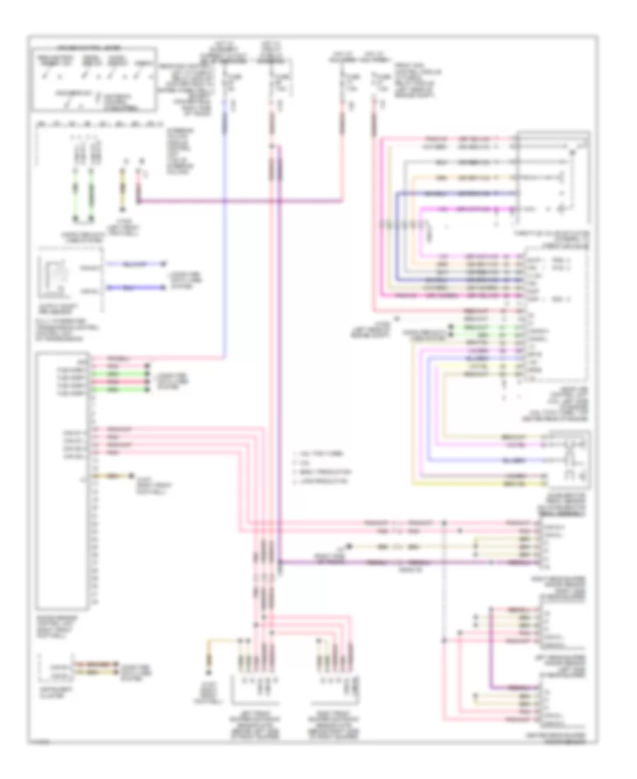
3.0L Turbo Diesel, Electronic Accelerator/Cruise/Idle Speed Control Wiring Diagram for Mercedes-Benz E350 2013
List of elements for 3.0L Turbo Diesel, Electronic Accelerator/Cruise/Idle Speed Control Wiring Diagram for Mercedes-Benz E350 2013:
- (in transmission) fully integrated transmission control control unit
- +5v
- Accelerate & set switch
- Accelerator pedal sensor (on accelerator pedal assembly)
- C12i
- C14i
- C2i
- C4i
- C5c
- Can b h
- Can b l
- Can c h
- Can c l
- Can e h
- Can e h can e1 h
- Can e l
- Can e l can e1 l
- Can h h
- Can h l
- Cdi control module (in right front wheelwell)
- Computer data lines system
- Cruise control lever
- Decelerate & set switch
- Distronic control (if equipped)
- Distronic control unit
- Distronic electronic controller unit (front center engine compt)
- Distronic radar sensor
- Distronic warning lamp (if equipped)
- Early production
- Front sam control module w/ fuse & relay module (left rear of engine compt)
- Fuse 5a
- Fuse 7.5a
- Gnd
- Hot at all times
- Hot w/ chassis circuit 87 relay energized
- Hot w/ circuit 15 relay energized
- Hot w/ quiescent current cutout relay energized
- Indicator switch
- Instrument cluster
- Late production
- Left front bumper distronic sensor (distronic plus) (behind left side of front bumper)
- Left rear bumper radar sensor (w/ active blind spot assist) (left side of rear bumper)
- Lvds n
- Lvds p
- M (+)
- M (-)
- Memory switch resume from
- Multifunction camera (w/ active lane keeping assist) (top center of front windshield)
- Off switch
- Output shaft rpm sensor
- Poti sig
- Rear sam control module w/ fuse & relay module (right side of trunk)
- Red
- Right front bumper distronic sensor (distronic plus) (behind right side of front bumper)
- Right rear bumper radar sensor (w/ active blind spot assist) (right side of rear bumper)
- Sh high
- Shield
- Sl low
- Sp1m
- Sp1s
- Sp2m
- Sp2s
- Steering column module control unit (top of steering column)
- Sv high
- Sv low
- Throttle valve actuator (integral to throttle valve actuator)
- U pwg
- Video & radar sensor system control unit (under right side of dash)
- Video n
- Video p
- W/ active park assist & pedestrian protection
- W/ active park assist w/o pedestrian protection
- W/ pedestrian protection w/o active park assist
- W/o active park assist
- W15/1 (right front footwell)
- W15/5 (left front footwell)
- W2 (right side of engine compt)
- W3/1 (behind right front fender)
- W7/8 (right side of trunk)
- X172/2-c1
- X26/38-c1
- X26/38-c2
- X26/38-c3
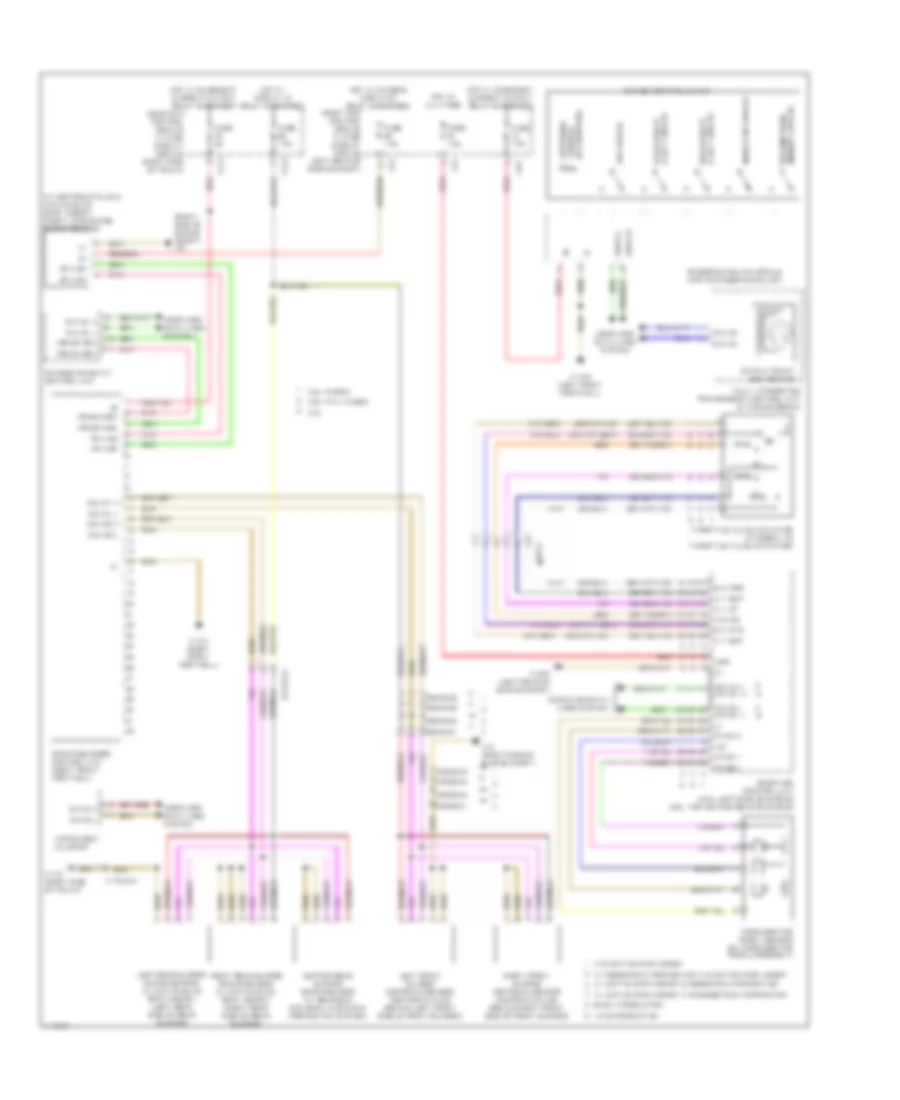
3.5L
3.5L, Cruise Control Wiring Diagram, Convertible for Mercedes-Benz E350 2013
List of elements for 3.5L, Cruise Control Wiring Diagram, Convertible for Mercedes-Benz E350 2013:
- (+) sv
- +5v
- 3.5l
- 30g
- 4.6l twin turbo
- Accel/ set sw
- Accelerator pedal sensor (on accelerator pedal assembly)
- C12i
- C14i
- C4i
- C5c
- Can 5h
- Can 5l
- Can b h
- Can b l
- Can e h
- Can e h can e1 h
- Can e l
- Can e l can e1 l
- Can s h
- Can s l
- Can s1 h
- Can s1 l
- Can s2 h
- Can s2 l
- Can-e h
- Can-e l
- Center rear bumper radar sensor
- Computer data lines system
- Cruise control lever
- Dcm
- Dcp
- Decel/ set sw
- Distronic control (if equipped)
- Early production
- Flex e-bm1
- Flex e-bp1
- Front sam control module w/ fuse & relay module (left rear of engine compt)
- Fully integrated transmission control control unit (in transmission)
- Fuse 5a
- Fuse 7.5a
- Hot at all times
- Hot w/ circuit 15 relay energized
- Hot w/ quiescent current cutout relay energized
- Indicator sw
- Instrument cluster
- Ip1s
- Ip2s
- Ipm
- Late production
- Left front bumper distronic sensor (dtr) (behind left side of front bumper)
- Left rear bumper radar sensor (left side of rear bumper)
- Me-sfi (me) control unit (3.5l: left side of engine) (4.6l twin turbo: top center rear of engine)
- Off sw
- Output shaft rpm sensor
- Pnk
- Radar sensor control unit (right front footwell)
- Rear sam control unit w/ fuse & relay module (convertible: in spare wheelwell) (except convertible: right side of trunk)
- Resume from memory sw
- Right front bumper distronic sensor (dtr) (behind right side of front bumper)
- Right rear bumper radar sensor (right side of rear bumper)
- Sp1s
- Sp2s
- Steering column module control unit (top of steering column)
- Svip
- Throttle valve actuator (integral to throttle valve)
- W15/5 (left front footwell)
- W15/7 (right front footwell)
- W16/5 (left rear of engine compt)
- W7 (right side of trunk)
- X26-c3
- X26/38
- X35/28-c2
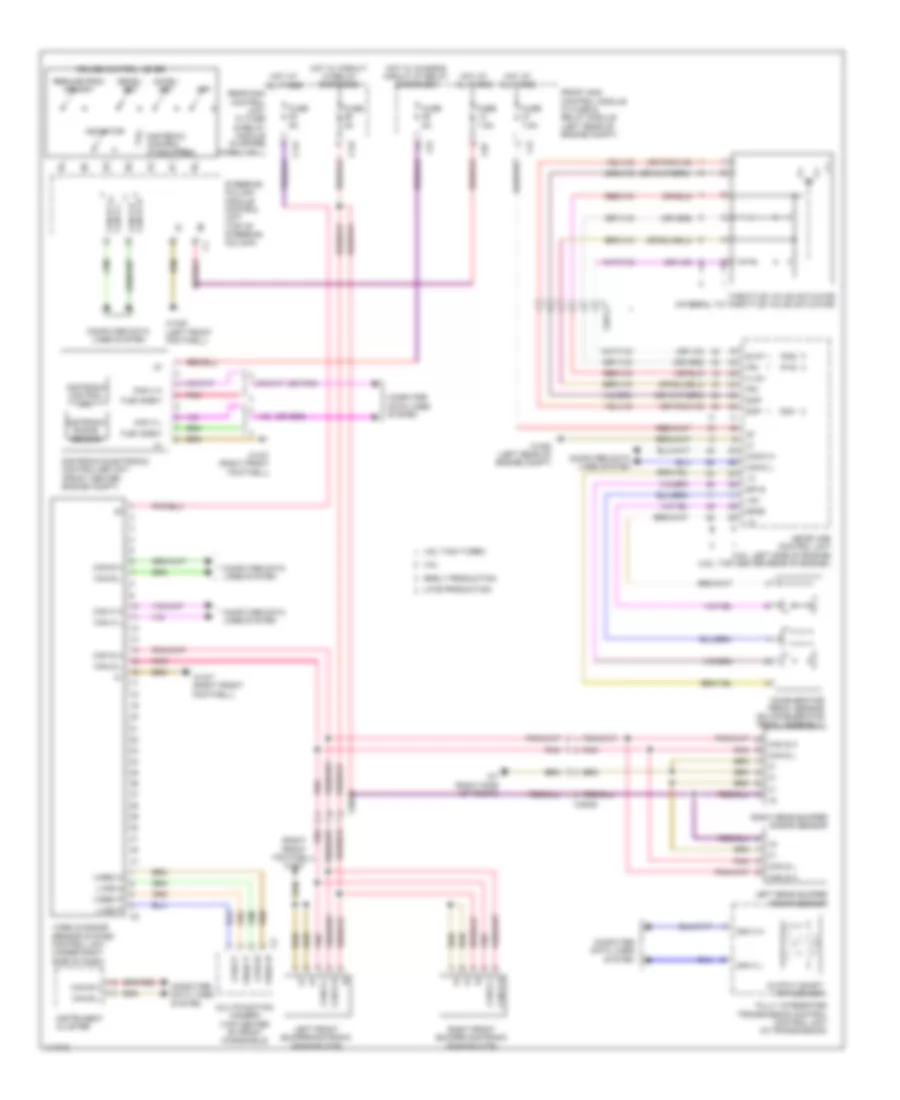
3.5L, Cruise Control Wiring Diagram, Coupe for Mercedes-Benz E350 2013
List of elements for 3.5L, Cruise Control Wiring Diagram, Coupe for Mercedes-Benz E350 2013:
- (+) sv
- +5v
- 3.5l
- 30g
- 4.6l twin turbo
- Accel/ set sw
- Accelerator pedal sensor (on accelerator pedal assembly)
- C12i
- C14i
- C4i
- C5c
- Can 5h
- Can 5l
- Can b h
- Can b l
- Can e h
- Can e h can e1 h
- Can e l
- Can e l can e1 l
- Can s h
- Can s l
- Can s1 h
- Can s1 l
- Can s2 h
- Can s2 l
- Can-e h
- Can-e l
- Center rear bumper radar sensor
- Computer data lines system
- Cruise control lever
- Dcm
- Dcp
- Decel/ set sw
- Distronic control (if equipped)
- Early production
- Flex e-bm1
- Flex e-bp1
- Front sam control module w/ fuse & relay module (left rear of engine compt)
- Fully integrated transmission control control unit (in transmission)
- Fuse 5a
- Fuse 7.5a
- Hot at all times
- Hot w/ circuit 15 relay energized
- Hot w/ quiescent current cutout relay energized
- Indicator sw
- Instrument cluster
- Ip1s
- Ip2s
- Ipm
- Late production
- Left front bumper distronic sensor (dtr) (behind left side of front bumper)
- Left rear bumper radar sensor (left side of rear bumper)
- Me-sfi (me) control unit (3.5l: left side of engine) (4.6l twin turbo: top center rear of engine)
- Off sw
- Output shaft rpm sensor
- Pnk
- Radar sensor control unit (right front footwell)
- Rear sam control unit w/ fuse & relay module (convertible: in spare wheelwell) (except convertible: right side of trunk)
- Resume from memory sw
- Right front bumper distronic sensor (dtr) (behind right side of front bumper)
- Right rear bumper radar sensor (right side of rear bumper)
- Sp1s
- Sp2s
- Steering column module control unit (top of steering column)
- Svip
- Throttle valve actuator (integral to throttle valve)
- W15/5 (left front footwell)
- W15/7 (right front footwell)
- W16/5 (left rear of engine compt)
- W7 (right side of trunk)
- X26-c3
- X26/38
- X35/28-c2
3.5L, Cruise Control Wiring Diagram, Sedan for Mercedes-Benz E350 2013
List of elements for 3.5L, Cruise Control Wiring Diagram, Sedan for Mercedes-Benz E350 2013:
- (-)
- (right side of engine compt) w2
- (w/ distronic plus & active blind spot assist) front long range radar sensor
- +5v
- 3.5l
- 3.5l hybrid
- 4.6l twin turbo
- A t dcm
- A t dcp
- A u up
- Accelerate & set switch
- Accelerator pedal sensor (on accelerator pedal assembly)
- C12i
- C14i
- C2i
- C4i
- C5c
- Can b h
- Can b l
- Can ch
- Can e h
- Can e h can e1 h
- Can e l
- Can e l can e1 l
- Can e1 h
- Can e1 l
- Can s1 h
- Can s1 l
- Can s2 h
- Can s2 l
- Center rear bumper radar sensor (w/ rear-end collision warning & protection system)
- Chassis gateway control unit
- Computer data lines system
- Cruise control lever
- Decelerate & set switch
- Distronic control (if equipped)
- E a ip1s
- E a ip2s
- Early production
- Fr a bm
- Fr a bp
- Fr3 bm rdu
- Fr3 bp rdu
- Front sam control module w/ fuse & relay module (left rear of engine compt)
- Fully integrated transmission control unit (in transmission)
- Fuse 5a
- Fuse 7.5a
- Hot at all times
- Hot w/ chassis circuit 87 relay energized
- Hot w/ circuit 15 relay energized
- Hot w/ quiescent current cutout relay energized
- Indicator switch
- Instrument cluster
- Late production
- Left front bumper distronic sensor (distronic plus) (behind left front side of front bumper)
- Left rear bumper radar sensor (w/ active blind spot assist) (left rear side of rear bumper)
- M r ipm
- Me-sfi (me) control unit (3.5l: left side of engine) (4.6l: top center rear of engine)
- Memory switch resume from
- Off switch
- Output shaft rpm sensor
- Pnk
- Pwg1-0
- Pwg1-1
- Pwg2-1
- Radar sensors control unit (right front footwell)
- Rear sam control module w/ fuse & relay module (right side of trunk)
- Red
- Right front bumper distronic sensor (distronic plus) (behind right front side of front bumper)
- Right rear bumper radar sensor (w/ active blind spot assist) (right rear side of rear bumper)
- Steering column module (top of steering column)
- Throttle valve actuator (integral to throttle valve actuator)
- Ubo
- W/ active park assist & pedestrian protection
- W/ active park assist w/o pedestrian protection
- W/ pedestrian protection w/o active park assist
- W/o active park assist
- W15/1 (right front footwell)
- W15/5 (left front footwell)
- W16/5 (left rear of engine compt)
- W2 (right side of engine compt)
- W7/8 (right side of trunk)
- X172/2-c1
- X26-c3
- X26/38-c1
- X26/38-c2
- X26/38-c3
- X26/38-c4
3.5L, Cruise Control Wiring Diagram, Wagon for Mercedes-Benz E350 2013
List of elements for 3.5L, Cruise Control Wiring Diagram, Wagon for Mercedes-Benz E350 2013:
- (-)
- (right side of engine compt) w2
- (w/ distronic plus & active blind spot assist) front long range radar sensor
- +5v
- 3.5l
- 3.5l hybrid
- 4.6l twin turbo
- A t dcm
- A t dcp
- A u up
- Accelerate & set switch
- Accelerator pedal sensor (on accelerator pedal assembly)
- C12i
- C14i
- C2i
- C4i
- C5c
- Can b h
- Can b l
- Can ch
- Can e h
- Can e h can e1 h
- Can e l
- Can e l can e1 l
- Can e1 h
- Can e1 l
- Can s1 h
- Can s1 l
- Can s2 h
- Can s2 l
- Center rear bumper radar sensor (w/ rear-end collision warning & protection system)
- Chassis gateway control unit
- Computer data lines system
- Cruise control lever
- Decelerate & set switch
- Distronic control (if equipped)
- E a ip1s
- E a ip2s
- Early production
- Fr a bm
- Fr a bp
- Fr3 bm rdu
- Fr3 bp rdu
- Front sam control module w/ fuse & relay module (left rear of engine compt)
- Fully integrated transmission control unit (in transmission)
- Fuse 5a
- Fuse 7.5a
- Hot at all times
- Hot w/ chassis circuit 87 relay energized
- Hot w/ circuit 15 relay energized
- Hot w/ quiescent current cutout relay energized
- Indicator switch
- Instrument cluster
- Late production
- Left front bumper distronic sensor (distronic plus) (behind left front side of front bumper)
- Left rear bumper radar sensor (w/ active blind spot assist) (left rear side of rear bumper)
- M r ipm
- Me-sfi (me) control unit (3.5l: left side of engine) (4.6l: top center rear of engine)
- Memory switch resume from
- Off switch
- Output shaft rpm sensor
- Pnk
- Pwg1-0
- Pwg1-1
- Pwg2-1
- Radar sensors control unit (right front footwell)
- Rear sam control module w/ fuse & relay module (right side of trunk)
- Red
- Right front bumper distronic sensor (distronic plus) (behind right front side of front bumper)
- Right rear bumper radar sensor (w/ active blind spot assist) (right rear side of rear bumper)
- Steering column module (top of steering column)
- Throttle valve actuator (integral to throttle valve actuator)
- Ubo
- W/ active park assist & pedestrian protection
- W/ active park assist w/o pedestrian protection
- W/ pedestrian protection w/o active park assist
- W/o active park assist
- W15/1 (right front footwell)
- W15/5 (left front footwell)
- W16/5 (left rear of engine compt)
- W2 (right side of engine compt)
- W7/8 (right side of trunk)
- X172/2-c1
- X26-c3
- X26/38-c1
- X26/38-c2
- X26/38-c3
- X26/38-c4
3.5L, Electronic Accelerator/Cruise/Idle Speed Control Wiring Diagram, Convertible for Mercedes-Benz E350 2013
List of elements for 3.5L, Electronic Accelerator/Cruise/Idle Speed Control Wiring Diagram, Convertible for Mercedes-Benz E350 2013:
- (+) 5v
- (or pnk)
- (right front footwell) w15/7
- +5v
- 3.5l
- 4.6l twin turbo
- Accel/ set
- Accelerator pedal sensor (on accelerator pedal assembly)
- C12i
- C14i
- C2i
- C4i
- C5c
- Can b h
- Can b l
- Can c h
- Can c l
- Can e h
- Can e l
- Can e l can e1 l
- Can e1 h can e h
- Can h h
- Can h l
- Can s h
- Can s l
- Can-c h
- Can-c l
- Computer data lines system
- Cruise control lever
- Dcm
- Dcp
- Decel/ set
- Distronic control (if equipped)
- Distronic control unit
- Distronic electronic controller unit (front center engine compt)
- Distronic radar sensor
- Early production
- Flex e-bm1
- Front sam control module w/ fuse & relay module (left rear of engine compt)
- Fully integrated transmission control control unit (in transmission)
- Fuse 5a
- Fuse 7.5a
- Hot at all times
- Hot w/ chassis circuit 87 relay energized
- Hot w/ circuit 15 relay energized
- Indicator
- Instrument cluster
- Ip1s
- Ip2s
- Ipm
- Late production
- Left front bumper distronic sensor (dtr)
- Left rear bumper radar sensor
- Lvds n
- Lvds p
- Me-sfi (me) control unit (3.5l: left side of engine) (4.6l: top center rear of engine )
- Multifunction camera (top center of front windshield)
- Off
- Output shaft rpm sensor
- Pnk
- Rear sam control unit w/ fuse & relay module (in spare wheelwell)
- Resume from memory
- Right front bumper distronic sensor (dtr)
- Right rear bumper radar sensor
- Sp1s
- Sp2s
- Steering column module control unit (top of steering column)
- Svip
- Throttle valve actuator (integral to throttle valve actuator)
- Video & radar sensor system control unit (under right side of dash)
- Video n
- Video p
- W15/5 (left front footwell)
- W15/7 (right front footwell)
- W16/5 (left rear of engine compt)
- W7 (right side of trunk)
- X26-c3
- X26/38
- X35/28
3.5L, Electronic Accelerator/Cruise/Idle Speed Control Wiring Diagram, Coupe for Mercedes-Benz E350 2013
List of elements for 3.5L, Electronic Accelerator/Cruise/Idle Speed Control Wiring Diagram, Coupe for Mercedes-Benz E350 2013:
- (+) 5v
- (or pnk)
- (right front footwell) w15/7
- +5v
- 3.5l
- 4.6l twin turbo
- Accel/ set
- Accelerator pedal sensor (on accelerator pedal assembly)
- C12i
- C14i
- C2i
- C4i
- C5c
- Can b h
- Can b l
- Can c h
- Can c l
- Can e h
- Can e l
- Can e l can e1 l
- Can e1 h can e h
- Can h h
- Can h l
- Can s h
- Can s l
- Can-c h
- Can-c l
- Computer data lines system
- Cruise control lever
- Dcm
- Dcp
- Decel/ set
- Distronic control (if equipped)
- Distronic control unit
- Distronic electronic controller unit (front center engine compt)
- Distronic radar sensor
- Early production
- Flex e-bm1
- Front sam control module w/ fuse & relay module (left rear of engine compt)
- Fully integrated transmission control control unit (in transmission)
- Fuse 5a
- Fuse 7.5a
- Hot at all times
- Hot w/ chassis circuit 87 relay energized
- Hot w/ circuit 15 relay energized
- Indicator
- Instrument cluster
- Ip1s
- Ip2s
- Ipm
- Late production
- Left front bumper distronic sensor (dtr)
- Left rear bumper radar sensor
- Lvds n
- Lvds p
- Me-sfi (me) control unit (3.5l: left side of engine) (4.6l: top center rear of engine )
- Multifunction camera (top center of front windshield)
- Off
- Output shaft rpm sensor
- Pnk
- Rear sam control unit w/ fuse & relay module (in spare wheelwell)
- Resume from memory
- Right front bumper distronic sensor (dtr)
- Right rear bumper radar sensor
- Sp1s
- Sp2s
- Steering column module control unit (top of steering column)
- Svip
- Throttle valve actuator (integral to throttle valve actuator)
- Video & radar sensor system control unit (under right side of dash)
- Video n
- Video p
- W15/5 (left front footwell)
- W15/7 (right front footwell)
- W16/5 (left rear of engine compt)
- W7 (right side of trunk)
- X26-c3
- X26/38
- X35/28
3.5L, Electronic Accelerator/Cruise/Idle Speed Control Wiring Diagram, Sedan for Mercedes-Benz E350 2013
List of elements for 3.5L, Electronic Accelerator/Cruise/Idle Speed Control Wiring Diagram, Sedan for Mercedes-Benz E350 2013:
- (-)
- (in transmission) fully integrated transmission control unit
- +5v
- 3.5l
- 3.5l hybrid
- 4.6l twin turbo
- A t dcm
- A t dcp
- A u up
- Accelerate & set switch
- Accelerator pedal sensor (on accelerator pedal assembly)
- C12i
- C14i
- C2i
- C4i
- C5c
- Can b h
- Can b l
- Can c h
- Can c l
- Can e h
- Can e h can e1 h
- Can e l
- Can e l can e1 l
- Can h h
- Can h l
- Computer data lines system
- Cruise control lever
- Decelerate & set switch
- Distronic control (if equipped)
- Distronic control unit
- Distronic electronic controller unit (front center engine compt)
- Distronic radar sensor
- Distronic warning lamp (if equipped)
- E a ip1s
- E a ip2s
- Early production
- Front sam control module w/ fuse & relay module (left rear of engine compt)
- Fuse 5a
- Fuse 7.5a
- Hot at all times
- Hot w/ chassis circuit 87 relay energized
- Hot w/ circuit 15 relay energized
- Hot w/ quiescent current cutout relay energized
- Indicator switch
- Instrument cluster
- Late production
- Left front bumper distronic sensor (distronic plus) (behind left side of front bumper)
- Left rear bumper radar sensor (w/ active blind spot assist) (left side of rear bumper)
- Lvds n
- Lvds p
- M r ipm
- Me-sfi (me) control unit (3.5l: left side of engine) (4.6l: top center rear of engine)
- Memory switch resume from
- Multi-function camera (top center of front windshield)
- Off switch
- Output shaft rpm sensor
- Pwg1-0
- Pwg1-1
- Pwg2-1
- Rear sam control module w/ fuse & relay module (right side of trunk)
- Red
- Right front bumper distronic sensor (distronic plus) (behind right side of front bumper)
- Right rear bumper radar sensor (w/ active blind spot assist) (right side of rear bumper)
- Sh high
- Shield
- Sl low
- Steering column module (top of steering column)
- Sv high
- Sv low
- Throttle valve actuator (integral to throttle valve actuator)
- Ubo
- Video & radar sensor system control unit (under right side of dash)
- Video n
- Video p
- W/ active park assist & pedestrian protection
- W/ active park assist w/o pedestrian protection
- W/ pedestrian protection w/o active park assist
- W/o active park assist
- W15/1 (right front footwell)
- W15/5 (left front footwell)
- W16/5 (left rear of engine compt)
- W2 (right front footwell)
- W2 (right side of engine compt)
- W7/8 (right side of trunk)
- X172/2-c1
- X26-c3
- X26/38-c1
- X26/38-c2
- X26/38-c3
3.5L, Electronic Accelerator/Cruise/Idle Speed Control Wiring Diagram, Wagon for Mercedes-Benz E350 2013
List of elements for 3.5L, Electronic Accelerator/Cruise/Idle Speed Control Wiring Diagram, Wagon for Mercedes-Benz E350 2013:
- (-)
- (in transmission) fully integrated transmission control unit
- +5v
- 3.5l
- 3.5l hybrid
- 4.6l twin turbo
- A t dcm
- A t dcp
- A u up
- Accelerate & set switch
- Accelerator pedal sensor (on accelerator pedal assembly)
- C12i
- C14i
- C2i
- C4i
- C5c
- Can b h
- Can b l
- Can c h
- Can c l
- Can e h
- Can e h can e1 h
- Can e l
- Can e l can e1 l
- Can h h
- Can h l
- Computer data lines system
- Cruise control lever
- Decelerate & set switch
- Distronic control (if equipped)
- Distronic control unit
- Distronic electronic controller unit (front center engine compt)
- Distronic radar sensor
- Distronic warning lamp (if equipped)
- E a ip1s
- E a ip2s
- Early production
- Front sam control module w/ fuse & relay module (left rear of engine compt)
- Fuse 5a
- Fuse 7.5a
- Hot at all times
- Hot w/ chassis circuit 87 relay energized
- Hot w/ circuit 15 relay energized
- Hot w/ quiescent current cutout relay energized
- Indicator switch
- Instrument cluster
- Late production
- Left front bumper distronic sensor (distronic plus) (behind left side of front bumper)
- Left rear bumper radar sensor (w/ active blind spot assist) (left side of rear bumper)
- Lvds n
- Lvds p
- M r ipm
- Me-sfi (me) control unit (3.5l: left side of engine) (4.6l: top center rear of engine)
- Memory switch resume from
- Multi-function camera (top center of front windshield)
- Off switch
- Output shaft rpm sensor
- Pwg1-0
- Pwg1-1
- Pwg2-1
- Rear sam control module w/ fuse & relay module (right side of trunk)
- Red
- Right front bumper distronic sensor (distronic plus) (behind right side of front bumper)
- Right rear bumper radar sensor (w/ active blind spot assist) (right side of rear bumper)
- Sh high
- Shield
- Sl low
- Steering column module (top of steering column)
- Sv high
- Sv low
- Throttle valve actuator (integral to throttle valve actuator)
- Ubo
- Video & radar sensor system control unit (under right side of dash)
- Video n
- Video p
- W/ active park assist & pedestrian protection
- W/ active park assist w/o pedestrian protection
- W/ pedestrian protection w/o active park assist
- W/o active park assist
- W15/1 (right front footwell)
- W15/5 (left front footwell)
- W16/5 (left rear of engine compt)
- W2 (right front footwell)
- W2 (right side of engine compt)
- W7/8 (right side of trunk)
- X172/2-c1
- X26-c3
- X26/38-c1
- X26/38-c2
- X26/38-c3