STARTING/CHARGING
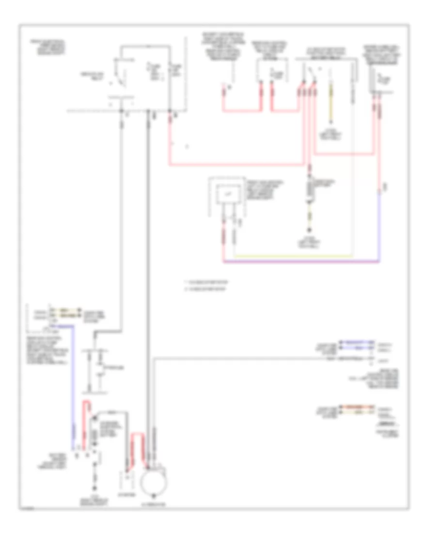
Charging Wiring Diagram, Convertible for Mercedes-Benz E350 2013

List of elements for Charging Wiring Diagram, Convertible for Mercedes-Benz E350 2013:
- (except convertible: right side of trunk) (convertible: in spare wheelwell) rear sam control module w/ fuse & relay module
- (spare wheelwell behind battery) additional battery realy circuit 30 additional fuse
- (w/ eco start/stop) function additional battery relay
- Additional battery
- Alternator
- Battery sensor (on battery terminal post)
- C19i
- C5h
- C9i
- Can b h
- Can b l
- Can c h
- Can c l
- Computer data lines system
- Decoupling relay
- Display
- Front electrical prefuse box (right rear of engine compt)
- Front sam control unit w/ fuse and relay module (left rear of engine compt)
- Fuse 100a
- Fuse 200a
- Fuse 400a 200a
- Fuse 7.5a
- Im1
- Instrument cluster
- Lin
- Lin c1
- Me-sfi (me) control module (3.5l: lleft side of engine) (4.6l: top center rear of engine)
- Mr8
- On board electrical system battery
- Pyrofuse
- Rear sam control module w/ fuse/ relay module (except convertible: right side of trunk) (convertible: in spare wheelwell)
- Rear sam control unit w/ fuse and relay module circuit 30 fuse
- Red
- Starter
- W/ eco start/stop
- W/o eco start/stop
- W10 (right rear of engine compt)
- W15/5 (left front footwell)
- X225
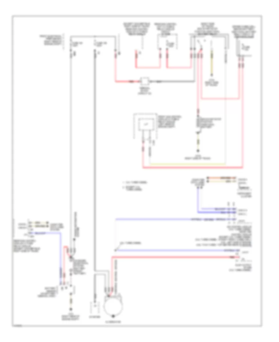
Charging Wiring Diagram, Coupe for Mercedes-Benz E350 2013
List of elements for Charging Wiring Diagram, Coupe for Mercedes-Benz E350 2013:
- (except convertible: right side of trunk) (convertible: in spare wheelwell) rear sam control module w/ fuse & relay module
- (spare wheelwell behind battery) additional battery realy circuit 30 additional fuse
- (w/ eco start/stop) function additional battery relay
- Additional battery
- Alternator
- Battery sensor (on battery terminal post)
- C19i
- C5h
- C9i
- Can b h
- Can b l
- Can c h
- Can c l
- Computer data lines system
- Decoupling relay
- Display
- Front electrical prefuse box (right rear of engine compt)
- Front sam control unit w/ fuse and relay module (left rear of engine compt)
- Fuse 100a
- Fuse 200a
- Fuse 400a 200a
- Fuse 7.5a
- Im1
- Instrument cluster
- Lin
- Lin c1
- Me-sfi (me) control module (3.5l: lleft side of engine) (4.6l: top center rear of engine)
- Mr8
- On board electrical system battery
- Pyrofuse
- Rear sam control module w/ fuse/ relay module (except convertible: right side of trunk) (convertible: in spare wheelwell)
- Rear sam control unit w/ fuse and relay module circuit 30 fuse
- Red
- Starter
- W/ eco start/stop
- W/o eco start/stop
- W10 (right rear of engine compt)
- W15/5 (left front footwell)
- X225
Charging Wiring Diagram, Sedan for Mercedes-Benz E350 2013
List of elements for Charging Wiring Diagram, Sedan for Mercedes-Benz E350 2013:
- (except convertible: right side of trunk) rear sam control module w/ fuse & relay module
- (right side of trunk) eco start/stop function additional battery relay
- (spare wheelwell behind battery) additional battery realy circuit 30 additional fuse
- 3.0l turbo diesel
- Alternator
- Battery sensor (on battery terminal post)
- C19i
- C5h
- C9i
- Can b h
- Can b l
- Can c h
- Can c l
- Cdi control module (3.0l turbo diesel) me-sfi (me) control module (except 3.0l turbo diesel) (3.0l turbo diesel: in right front wheelwell) (3.5l: left side of engine) (4.6l twin turbo: top center rear of engine)
- Computer data lines system
- Display
- Eco start/stop function additional battery
- Except 3.0l
- Front electrical prefuse box (right rear of engine compt)
- Front sam control module w/ fuse & relay module (left rear of engine compt)
- Fuse 100a
- Fuse 150 150a
- Fuse 159 400a
- Fuse 7.5a
- Glow output stage (3.0l turbo diesel)
- Im1
- Instrument cluster
- Lin
- Lin c1
- Mr8
- On board electrical system battery (front battery)
- Power distribution system
- Rear sam control module w/ fuse/ relay module (except convertible: right side of trunk)
- Rear sam control unit w/ fuse & relay module circuit 30 fuse
- Red
- Starter
- Terminal block (circuit 30)
- Turbo diesel
- W10 (right rear of engine compt)
- W7/6 (right side of trunk)
- W7/8 (right side of trunk)
Charging Wiring Diagram, Wagon for Mercedes-Benz E350 2013
List of elements for Charging Wiring Diagram, Wagon for Mercedes-Benz E350 2013:
- (except convertible: right side of trunk) rear sam control module w/ fuse & relay module
- (right side of trunk) eco start/stop function additional battery relay
- (spare wheelwell behind battery) additional battery realy circuit 30 additional fuse
- 3.0l turbo diesel
- Alternator
- Battery sensor (on battery terminal post)
- C19i
- C5h
- C9i
- Can b h
- Can b l
- Can c h
- Can c l
- Cdi control module (3.0l turbo diesel) me-sfi (me) control module (except 3.0l turbo diesel) (3.0l turbo diesel: in right front wheelwell) (3.5l: left side of engine) (4.6l twin turbo: top center rear of engine)
- Computer data lines system
- Display
- Eco start/stop function additional battery
- Except 3.0l
- Front electrical prefuse box (right rear of engine compt)
- Front sam control module w/ fuse & relay module (left rear of engine compt)
- Fuse 100a
- Fuse 150 150a
- Fuse 159 400a
- Fuse 7.5a
- Glow output stage (3.0l turbo diesel)
- Im1
- Instrument cluster
- Lin
- Lin c1
- Mr8
- On board electrical system battery (front battery)
- Power distribution system
- Rear sam control module w/ fuse/ relay module (except convertible: right side of trunk)
- Rear sam control unit w/ fuse & relay module circuit 30 fuse
- Red
- Starter
- Terminal block (circuit 30)
- Turbo diesel
- W10 (right rear of engine compt)
- W7/6 (right side of trunk)
- W7/8 (right side of trunk)
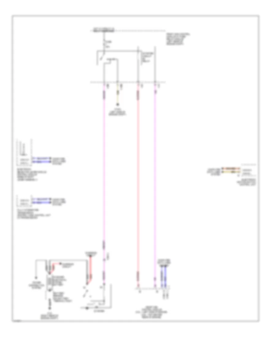
Starting Wiring Diagram, Convertible for Mercedes-Benz E350 2013
List of elements for Starting Wiring Diagram, Convertible for Mercedes-Benz E350 2013:
- Battery sensor (on battery terminal post)
- C15m
- C3m
- C4i
- C6i
- Can b h
- Can b l
- Can c h
- Can c l
- Charging circuit
- Computer data lines system
- Electronic ignition switch control unit
- Electronic selector lever module control module (base of shift lever assembly)
- Front sam control module w/ fuse/ relay module (left rear of engine compt)
- Fully integrated transmission control (vgs) control unit (in transmission)
- Fuse 20a
- Hot w/ circuit 15 relay energized
- Me-sfi (me) control module (3.5l: lleft side of engine) (4.6l: top center rear of engine)
- On board electrical system battery
- P r n d- d+
- Power distribution system
- Red
- Starter
- Starter circuit relay
- W10 (right rear of engine compt)
- W16/3 (left side of engine compt)
- X26-c1
Starting Wiring Diagram, Coupe for Mercedes-Benz E350 2013
List of elements for Starting Wiring Diagram, Coupe for Mercedes-Benz E350 2013:
- Battery sensor (on battery terminal post)
- C15m
- C3m
- C4i
- C6i
- Can b h
- Can b l
- Can c h
- Can c l
- Charging circuit
- Computer data lines system
- Electronic ignition switch control unit
- Electronic selector lever module control module (base of shift lever assembly)
- Front sam control module w/ fuse/ relay module (left rear of engine compt)
- Fully integrated transmission control (vgs) control unit (in transmission)
- Fuse 20a
- Hot w/ circuit 15 relay energized
- Me-sfi (me) control module (3.5l: lleft side of engine) (4.6l: top center rear of engine)
- On board electrical system battery
- P r n d- d+
- Power distribution system
- Red
- Starter
- Starter circuit relay
- W10 (right rear of engine compt)
- W16/3 (left side of engine compt)
- X26-c1
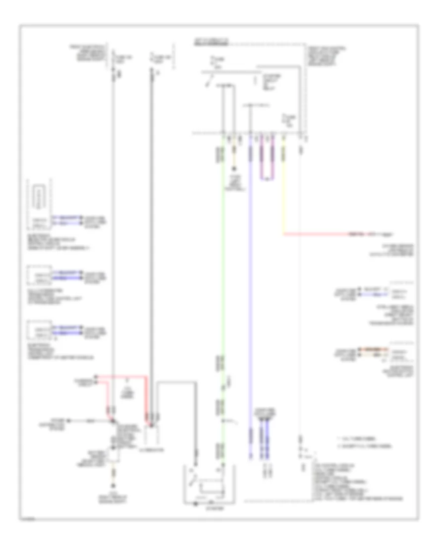
Starting Wiring Diagram, Sedan for Mercedes-Benz E350 2013
List of elements for Starting Wiring Diagram, Sedan for Mercedes-Benz E350 2013:
- 3.0l turbo diesel
- Alternator
- Battery sensor (on battery terminal post)
- C15m
- C3m
- C4i
- C6i
- Can b h
- Can b l
- Can c h
- Can c l
- Cdi control module (3.0l turbo diesel) me-sfi (me) control module (except 3.0l turbo diesel) (3.0l turbo diesel: in right front wheelwell) (3.5l: left side of engine) (4.6l twin turbo: top center rear of engine)
- Charging circuit
- Computer data lines system
- Electronic ignition switch control unit
- Electronic selector lever module control module (base of shift lever assembly)
- Electronic transmission control unit (under front of center console)
- Except 3.0l turbo diesel
- Front electrical prefuse box (right rear of engine compt)
- Front sam control module w/ fuse/ relay module (left rear of engine compt)
- Fully integrated transmission control (vgs) control unit (in transmission)
- Fuse 150 150a
- Fuse 159 400a
- Fuse 15a
- Fuse 20a
- Hot w/ circuit 15 relay energized
- Intelligent servo module for direct select (bottom of transmission housing)
- Mr8
- Nca
- On board electrical system battery (front battery)
- Oxygen sensor upstream of catalytic converter
- P r n d- d+
- Power distribution system
- Red
- Starter
- Starter circuit relay
- Str
- W10 (right rear of engine compt)
- W15/5 (left front footwell)
- X26-c1
Starting Wiring Diagram, Wagon for Mercedes-Benz E350 2013
List of elements for Starting Wiring Diagram, Wagon for Mercedes-Benz E350 2013:
- 3.0l turbo diesel
- Alternator
- Battery sensor (on battery terminal post)
- C15m
- C3m
- C4i
- C6i
- Can b h
- Can b l
- Can c h
- Can c l
- Cdi control module (3.0l turbo diesel) me-sfi (me) control module (except 3.0l turbo diesel) (3.0l turbo diesel: in right front wheelwell) (3.5l: left side of engine) (4.6l twin turbo: top center rear of engine)
- Charging circuit
- Computer data lines system
- Electronic ignition switch control unit
- Electronic selector lever module control module (base of shift lever assembly)
- Electronic transmission control unit (under front of center console)
- Except 3.0l turbo diesel
- Front electrical prefuse box (right rear of engine compt)
- Front sam control module w/ fuse/ relay module (left rear of engine compt)
- Fully integrated transmission control (vgs) control unit (in transmission)
- Fuse 150 150a
- Fuse 159 400a
- Fuse 15a
- Fuse 20a
- Hot w/ circuit 15 relay energized
- Intelligent servo module for direct select (bottom of transmission housing)
- Mr8
- Nca
- On board electrical system battery (front battery)
- Oxygen sensor upstream of catalytic converter
- P r n d- d+
- Power distribution system
- Red
- Starter
- Starter circuit relay
- Str
- W10 (right rear of engine compt)
- W15/5 (left front footwell)
- X26-c1