TRANSMISSION
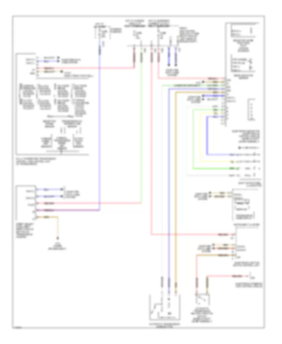
Transmission Wiring Diagram, Convertible for Mercedes-Benz E350 2013

List of elements for Transmission Wiring Diagram, Convertible for Mercedes-Benz E350 2013:
- 30g
- 30z
- 58d
- Automatic transmission mode button
- Automatic transmission neutral position switch (base of shift lever assembly)
- C124
- C2i
- C5c
- C9g
- Can b h
- Can b l
- Can c h
- Can c l
- Clutch control solenoid valve k1
- Clutch control solenoid valve k2
- Clutch control solenoid valve k3
- Computer data lines system
- Direct select intelligent servo module (bottom of transmission housing)
- Electronic ignition switch control unit
- Electronic selector lever module control module (base of shift lever assembly)
- Electronic steering lock control module
- Front sam control module w/ fuse/ relay module (left rear of engine compt)
- Fully integrated transmission control (vgs) control unit (in transmission)
- Fuse 10a
- Fuse 20a
- Fuse 5a
- Gear ind
- Gear indicator sensor
- Gnd
- Hot at all times
- Hot w/ chassis circuit 87 relay energized
- Hot w/ quiescent current cutout relay energized
- Instrument cluster
- Interior fuse box
- Internal transmission speed rpm sensor
- Multidisk brake control solenoid valve b1
- Multidisk brake control solenoid valve b2
- Multidisk brake control solenoid valve b3
- Output shaft rpm sensor
- P not
- Prnd
- R/p s (+)
- R/p s (-)
- Selection range sensor
- Selector lever positions r & p locking solenoid
- Shift gate symbol illumination
- Sig
- Tipp (+)
- Tipp (-)
- Tipp (masse)
- Tipp (plus)
- Torque converter lockup clutch control solenoid valve
- Transmission mode display
- Transmission oil temperature sensor
- Turbine wheel rpm sensor
- W15/7 (right front footwell)
- W18 (under driver's seat)
- Working pressure control solenoid valve
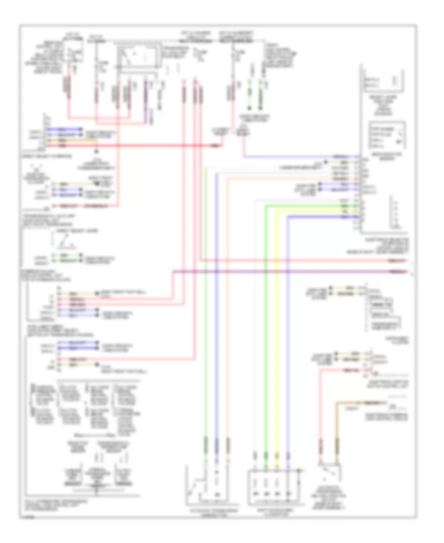
Transmission Wiring Diagram, Coupe for Mercedes-Benz E350 2013
List of elements for Transmission Wiring Diagram, Coupe for Mercedes-Benz E350 2013:
- 30g
- 30z
- 58d
- Automatic transmission mode button
- Automatic transmission neutral position switch (base of shift lever assembly)
- C124
- C2i
- C5c
- C9g
- Can b h
- Can b l
- Can c h
- Can c l
- Clutch control solenoid valve k1
- Clutch control solenoid valve k2
- Clutch control solenoid valve k3
- Computer data lines system
- Direct select intelligent servo module (bottom of transmission housing)
- Electronic ignition switch control unit
- Electronic selector lever module control module (base of shift lever assembly)
- Electronic steering lock control module
- Front sam control module w/ fuse/ relay module (left rear of engine compt)
- Fully integrated transmission control (vgs) control unit (in transmission)
- Fuse 10a
- Fuse 20a
- Fuse 5a
- Gear ind
- Gear indicator sensor
- Gnd
- Hot at all times
- Hot w/ chassis circuit 87 relay energized
- Hot w/ quiescent current cutout relay energized
- Instrument cluster
- Interior fuse box
- Internal transmission speed rpm sensor
- Multidisk brake control solenoid valve b1
- Multidisk brake control solenoid valve b2
- Multidisk brake control solenoid valve b3
- Output shaft rpm sensor
- P not
- Prnd
- R/p s (+)
- R/p s (-)
- Selection range sensor
- Selector lever positions r & p locking solenoid
- Shift gate symbol illumination
- Sig
- Tipp (+)
- Tipp (-)
- Tipp (masse)
- Tipp (plus)
- Torque converter lockup clutch control solenoid valve
- Transmission mode display
- Transmission oil temperature sensor
- Turbine wheel rpm sensor
- W15/7 (right front footwell)
- W18 (under driver's seat)
- Working pressure control solenoid valve
Transmission Wiring Diagram, Sedan (1 of 2) for Mercedes-Benz E350 2013
List of elements for Transmission Wiring Diagram, Sedan (1 of 2) for Mercedes-Benz E350 2013:
- (coupe: right side of trunk)
- (not used)
- (or red)
- (right front footwell)
- (right front footwell) w15/1
- 12v
- 30g
- 30z
- 58d
- Automatic transmission mode button
- Automatic transmission neutral position switch (base of shift lever assembly)
- C10r
- C10t
- C11c
- C19i
- C9g
- Can b h
- Can b l
- Can c h
- Can c l
- Can e h
- Can e l
- Can-c h
- Can-c l
- Can-e h
- Can-e l
- Clutch control solenoid valve k1
- Clutch control solenoid valve k2
- Clutch control solenoid valve k3
- Computer data lines system
- Direct select interface
- Direct select lever
- Electric transmission oil pump
- Electronic ignition switch control unit
- Electronic selector lever module control module (base of shift lever assembly)
- Electronic steering lock control module
- Front sam control module w/ fuse/ relay module (left rear of engine compt)
- Fully integrated transmission control (vgs) control unit (in transmission)
- Fuse 10a
- Fuse 15a
- Fuse 5a
- Fuse 7.5a
- Gear ind
- Gear indicator sensor
- Gnd
- Hot at all times
- Hot w/ chassis circuit 87 relay energized
- Hot w/ quiescent current cutout relay energized
- Instrument cluster
- Intelligent servo module for direct select (bottom of transmission housing)
- Internal transmission speed rpm sensor
- Multidisk brake control solenoid valve b1
- Multidisk brake control solenoid valve b2
- Multidisk brake control solenoid valve b3
- Output shaft rpm sensor
- P not
- Prnd
- R/p s (+)
- R/p s (-)
- Rear sam control unit w/ fuse & relay module (convertible: in spare wheelwell)
- Red
- Select lever positions r & p locking solenoid
- Selection range sensor
- Shift gate symbol illumination
- Sig
- Steering column module control unit (top of steering column)
- Tipp (+)
- Tipp (-)
- Tipp (masse)
- Tipp (plus)
- Torque converter lockup clutch control solenoid valve
- Transmission mode display
- Transmission oil auxiliary pump control unit (bottom of transmission)
- Transmission oil auxiliary pump relay
- Transmission oil temperature sensor
- Turbine wheel rpm sensor
- W/ direct select
- W/o direct select
- W15/1
- W15/1 (right front footwell)
- W18 (under driver's seat)
- W19 (under front passenger's seat)
- Working pressure control solenoid valve
- X190-c1
- X83/11-c2
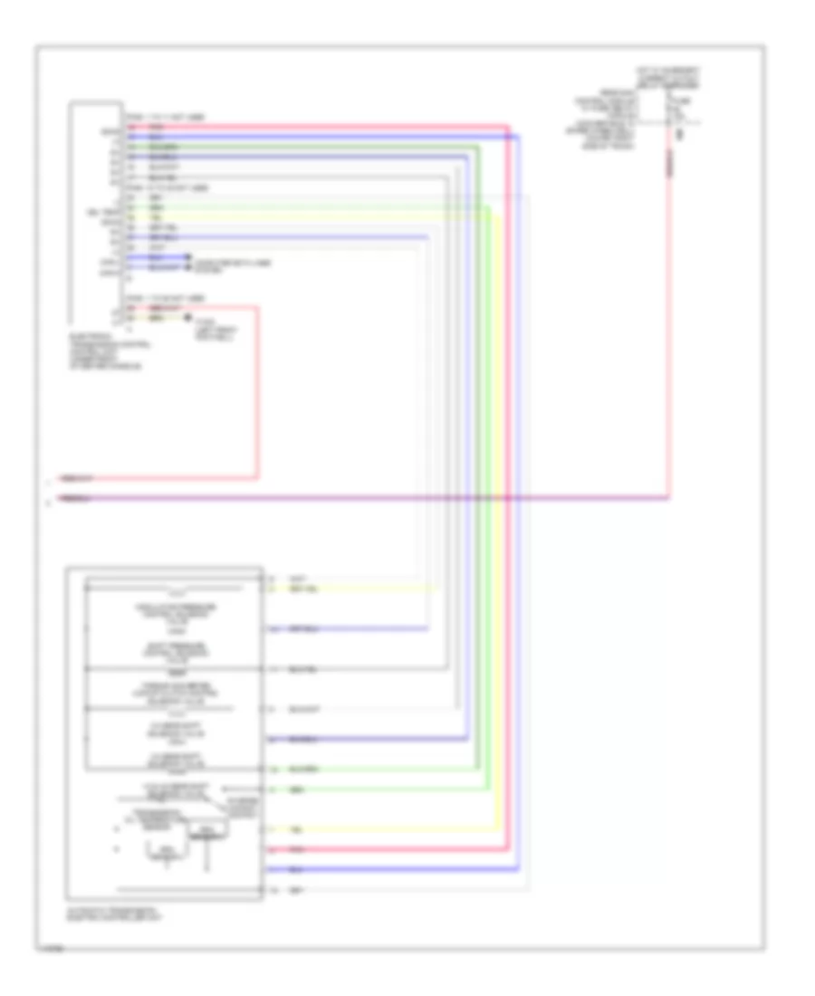
Transmission Wiring Diagram, Sedan (2 of 2) for Mercedes-Benz E350 2013
List of elements for Transmission Wiring Diagram, Sedan (2 of 2) for Mercedes-Benz E350 2013:
- (+)
- (-)
- 1-2 & 4-5 gear shift solenoid valve
- 2-3 gear shift solenoid valve
- 3-4 gear shift solenoid valve
- Automatic transmission electric controller unit
- Can-h
- Can-l
- Computer data lines system
- Dz-n2
- Dz-n3
- Electronic transmission control control unit (under front of center console)
- Fuse 15a
- Hot w/ quiescent current cutout relay energized
- Ism
- Modulating pressure control solenoid valve
- Oel temp
- Pins: 1 to 11 not used
- Pins: 1 to 28 not used
- Pins: 18 to 32 not used
- Pnk
- Rear sam control module w/ fuse/ relay module (convertible: in spare wheelwell) (coupe: right side of trunk)
- Rpm sensor 2
- Rpm sensor 3
- Shift pressure control solenoid valve
- Starter lockout contact
- Torque converter lockup clutch control solenoid valve
- Transmission oil temperature sensor
- W15/2 (left front footwell)
Transmission Wiring Diagram, Wagon (1 of 2) for Mercedes-Benz E350 2013
List of elements for Transmission Wiring Diagram, Wagon (1 of 2) for Mercedes-Benz E350 2013:
- (coupe: right side of trunk)
- (not used)
- (or red)
- (right front footwell)
- (right front footwell) w15/1
- 12v
- 30g
- 30z
- 58d
- Automatic transmission mode button
- Automatic transmission neutral position switch (base of shift lever assembly)
- C10r
- C10t
- C11c
- C19i
- C9g
- Can b h
- Can b l
- Can c h
- Can c l
- Can e h
- Can e l
- Can-c h
- Can-c l
- Can-e h
- Can-e l
- Clutch control solenoid valve k1
- Clutch control solenoid valve k2
- Clutch control solenoid valve k3
- Computer data lines system
- Direct select interface
- Direct select lever
- Electric transmission oil pump
- Electronic ignition switch control unit
- Electronic selector lever module control module (base of shift lever assembly)
- Electronic steering lock control module
- Front sam control module w/ fuse/ relay module (left rear of engine compt)
- Fully integrated transmission control (vgs) control unit (in transmission)
- Fuse 10a
- Fuse 15a
- Fuse 5a
- Fuse 7.5a
- Gear ind
- Gear indicator sensor
- Gnd
- Hot at all times
- Hot w/ chassis circuit 87 relay energized
- Hot w/ quiescent current cutout relay energized
- Instrument cluster
- Intelligent servo module for direct select (bottom of transmission housing)
- Internal transmission speed rpm sensor
- Multidisk brake control solenoid valve b1
- Multidisk brake control solenoid valve b2
- Multidisk brake control solenoid valve b3
- Output shaft rpm sensor
- P not
- Prnd
- R/p s (+)
- R/p s (-)
- Rear sam control unit w/ fuse & relay module (convertible: in spare wheelwell)
- Red
- Select lever positions r & p locking solenoid
- Selection range sensor
- Shift gate symbol illumination
- Sig
- Steering column module control unit (top of steering column)
- Tipp (+)
- Tipp (-)
- Tipp (masse)
- Tipp (plus)
- Torque converter lockup clutch control solenoid valve
- Transmission mode display
- Transmission oil auxiliary pump control unit (bottom of transmission)
- Transmission oil auxiliary pump relay
- Transmission oil temperature sensor
- Turbine wheel rpm sensor
- W/ direct select
- W/o direct select
- W15/1
- W15/1 (right front footwell)
- W18 (under driver's seat)
- W19 (under front passenger's seat)
- Working pressure control solenoid valve
- X190-c1
- X83/11-c2
Transmission Wiring Diagram, Wagon (2 of 2) for Mercedes-Benz E350 2013
List of elements for Transmission Wiring Diagram, Wagon (2 of 2) for Mercedes-Benz E350 2013:
- (+)
- (-)
- 1-2 & 4-5 gear shift solenoid valve
- 2-3 gear shift solenoid valve
- 3-4 gear shift solenoid valve
- Automatic transmission electric controller unit
- Can-h
- Can-l
- Computer data lines system
- Dz-n2
- Dz-n3
- Electronic transmission control control unit (under front of center console)
- Fuse 15a
- Hot w/ quiescent current cutout relay energized
- Ism
- Modulating pressure control solenoid valve
- Oel temp
- Pins: 1 to 11 not used
- Pins: 1 to 28 not used
- Pins: 18 to 32 not used
- Pnk
- Rear sam control module w/ fuse/ relay module (convertible: in spare wheelwell) (coupe: right side of trunk)
- Rpm sensor 2
- Rpm sensor 3
- Shift pressure control solenoid valve
- Starter lockout contact
- Torque converter lockup clutch control solenoid valve
- Transmission oil temperature sensor
- W15/2 (left front footwell)